Steering Angle Sensor Output (C1434). Malfunction in Yaw Rate Sensor (C1436). Steering Angle Sensor Initialization Incomplete (C1439,C1445)
Steering Angle Sensor Output (C1434)
DESCRIPTION
The skid control ECU (brake actuator assembly) receives signals from the steering angle sensor via CAN communication.
HINT:
If there is a malfunction in the bus lines between the steering angle sensor and the CAN communication system, DTC U0126 (Lost Communication With Steering Angle Sensor Module) is output. When U0126 is output together with C1434, inspect and repair the trouble areas indicated by U0126 first.
DTCs may be stored if one of the following occurs:
- Steering angle sensor zero point value malfunction.
- Steering angle sensor signal malfunction.
- Steering angle sensor signal stuck malfunction.
- Steering angle sensor and the yaw rate sensor values inconsistent.
- Steering angle sensor installation abnormality.
DTC No. | Detection Item | DTC Detection Condition | Trouble Area |
|---|---|---|---|
C1434 |
Steering Angle Sensor Output |
Any of the following is detected:
|
|
Vehicle Condition |
|||||||
|---|---|---|---|---|---|---|---|
Pattern 1 | Pattern 2 | Pattern 3 | Pattern 4 | Pattern 5 | Pattern 6 |
||
Diagnosis Condition |
The steering angle sensor value changes by less than 5 deg. |
- |
- |
- |
- |
○ |
- |
Malfunction Status |
The difference between the zero point of the steering angle sensor and the estimated zero point exceeds 15 deg. |
○ |
- |
- |
- |
- |
- |
The offset value of the steering angle sensor is -13.5 deg. or less or 13.5 deg. or more. |
- |
○ |
- |
- |
- |
- |
|
The steering angle sensor value exceeds a specified value. |
- |
- |
○ |
- |
- |
- |
|
The change of the steering angle sensor value within 0.02 seconds is abnormal. |
- |
- |
- |
○ |
- |
- |
|
Both left and right turns have been recognized. |
- |
- |
- |
- |
○ |
- |
|
There is a difference between the skid control ECU (brake actuator assembly) estimated value and the steering angle sensor value due to an abnormal steering angle sensor value. |
- |
- |
- |
- |
- |
○ |
|
Detection Time |
- |
- |
0.3 seconds or more |
- |
- |
- |
|
Number of Trips |
1 trip |
1 trip |
1 trip |
1 trip |
1 trip |
1 trip |
|
HINT:
DTC will be output when conditions for either of the patterns in the table above are met.
WIRING DIAGRAM
Refer to DTC C1231.
Click here 
NOTICE:
Inspect the fuses for circuits related to this system before performing the following procedure.
HINT:
- When U0073, U0123 and/or U0126 is output together with C1434, inspect and repair the trouble areas indicated by U0073, U0123 and/or U0126 first.
Click here
- When a speed sensor or the yaw rate and acceleration sensor (airbag sensor assembly) is malfunctioning, DTCs for the steering angle sensor may be stored even though the steering angle sensor is normal. When DTCs for a speed sensor or yaw rate and acceleration sensor (airbag sensor assembly) are output together with DTCs for the steering angle sensor, inspect and repair the speed sensor or yaw rate and acceleration sensor (airbag sensor assembly) first, and then inspect and repair the steering angle sensor.
PROCEDURE
CHECK DTC
(a) Clear the DTCs.
Chassis > ABS/VSC/TRAC/EPB > Clear DTCs(b) Turn the engine switch off.
(c) Turn the engine switch on (IG) again and check that no CAN communication system DTCs are output.
Click here
(d) Start the engine.
(e) Drive the vehicle at a speed of 50 km/h and turn the steering wheel to the right and left and then check that no speed sensor or yaw rate and acceleration sensor (airbag sensor assembly) DTCs are output.
Chassis > ABS/VSC/TRAC/EPB > Trouble CodesResult | Proceed to |
|---|---|
No CAN communication system, speed sensor, or yaw rate and acceleration sensor (airbag sensor assembly) DTCs are output |
A |
CAN communication system DTCs are output |
B |
Speed sensor and/or yaw rate and acceleration sensor (airbag sensor assembly) DTCs are output |
C |
HINT:
- If a speed sensor or the yaw rate and acceleration sensor (airbag sensor assembly) is malfunctioning, DTCs for the steering angle sensor may be stored even though the steering angle sensor is normal.
- If speed sensor and yaw rate and acceleration sensor (airbag sensor assembly) DTCs are output simultaneously, repair these malfunctions and then inspect the steering angle sensor.
| B |  |
INSPECT CAN COMMUNICATION SYSTEM |
| C | |
REPAIR CIRCUIT INDICATED BY OUTPUT DTC |
|

CHECK STEERING ANGLE SENSOR INSTALLATION
(a) Turn the engine switch off.
(b) Check that the steering angle sensor has been installed properly.
Click here
OK:
The steering angle sensor installation is normal.
| NG | |
INSTALL STEERING ANGLE SENSOR CORRECTLY |
|
CHECK HARNESS AND CONNECTOR (POWER SOURCE TERMINAL)
(a) Remove the steering wheel and column cover. |
|
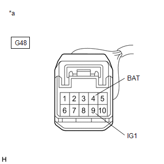
(b) Make sure that there is no looseness at the locking part and the connecting part of the connector.
OK:
The connector is securely connected.
(c) Disconnect the G48 steering angle sensor connector.
(d) Check both the connector case and the terminals for deformation and corrosion.
OK:
No deformation or corrosion.
(e) Measure the voltage according to the value(s) in the table below.
Standard Voltage:
Tester Connection | Condition | Specified Condition |
|---|---|---|
G48-4 (BAT) - Body ground |
Always |
11 to 14 V |
G48-9 (IG1) - Body ground |
Engine switch on (IG) |
11 to 14 V |
| NG | |
REPAIR OR REPLACE HARNESS OR CONNECTOR (POWER SOURCE CIRCUIT) |
|
CHECK HARNESS AND CONNECTOR (GROUND TERMINAL)
(a) Turn the engine switch off. |
|
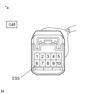
(b) Measure the resistance according to the value(s) in the table below.
NOTICE:
Before measuring the resistance of the steering angle sensor, turn the engine switch off and leave the vehicle for 1 minute or more without operating the key or switches, or opening or closing the doors.
Standard Resistance:
Tester Connection | Condition | Specified Condition |
|---|---|---|
G48-6 (ESS) - Body ground |
1 minute after engine switch off |
Below 1 Ω |
| OK | |
REPLACE STEERING ANGLE SENSOR |
| NG | |
REPAIR OR REPLACE HARNESS OR CONNECTOR (GROUND CIRCUIT) |
Malfunction in Yaw Rate Sensor (C1436)
DESCRIPTION
This DTC is stored when the skid control ECU (brake actuator assembly) detects improper installation of the yaw rate and acceleration sensor (airbag sensor assembly) or an abnormality in the difference between the yaw rate sensor value and the control value estimated based on the acceleration sensor, steering angle sensor and speed sensor signals.
The airbag sensor assembly has a built-in yaw rate and acceleration sensor and detects the vehicle condition.
DTC No. | Detection Item | DTC Detection Condition | Trouble Area |
|---|---|---|---|
C1436 |
Malfunction in Yaw Rate Sensor |
Difference between the yaw rate sensor value and the control value estimated inside the skid control ECU (brake actuator assembly) is abnormal. |
|
NOTICE:
After replacing or reinstalling the yaw rate and acceleration sensor (airbag sensor assembly), perform system variant learning and acceleration sensor zero point calibration.
Click here 
PROCEDURE
READ VALUE USING TECHSTREAM (YAW RATE AND ACCELERATION SENSOR)
(a) Connect the Techstream to the DLC3.
(b) Turn the engine switch on (IG).
(c) Enter the following menus: Chassis / ABS/VSC/TRAC/EPB / Data List.
Chassis > ABS/VSC/TRAC/EPB > Data ListTester Display | Measurement Item | Range | Normal Condition | Diagnostic Note |
|---|---|---|---|---|
Yaw Rate Sensor |
Yaw rate sensor |
Min.: -128°/s, Max.: 127°/s |
Vehicle stopped: 0°/s Turning right: -128 to 0°/s Turning left: 0 to 127°/s |
- |
Yaw Rate Sensor
(d) Check the yaw rate and acceleration sensor (airbag sensor assembly) output value displayed on the Techstream.
Result | Proceed to |
|---|---|
The value of Yaw Rate Sensor is 0°/s when the vehicle is stopped and the output value fluctuate when the vehicle turning right or left |
A |
The value of Yaw Rate Sensor is not 0°/s when the vehicle is stopped |
B |
The value of Yaw Rate Sensor is 0°/s when the vehicle is stopped and the output value does not fluctuate when the vehicle turning right or left |
C |
| B |  |
REPLACE AIRBAG SENSOR ASSEMBLY |
| C | |
USE SIMULATION METHOD TO CHECK |
|

CHECK STEERING ANGLE SENSOR ZERO POINT CALIBRATION
(a) Turn the engine switch off.
(b) Drive the vehicle straight ahead at 15 km/h or more for at least 1 second.
(c) Check that the steering wheel is correctly centered while driving straight ahead.
HINT:
If front wheel alignment and steering are adjusted as a result of an off-center steering wheel, acquire the yaw rate and acceleration sensor zero point again after the adjustments are completed.
OK:
The steering wheel is correctly centered.
| NG | |
ADJUST FRONT WHEEL ALIGNMENT OR STEERING |
|
CHECK AIRBAG SENSOR ASSEMBLY INSTALLATION
(a) Check that the yaw rate and acceleration sensor (airbag sensor assembly) has been installed properly.
Click here
OK:
The yaw rate and acceleration sensor (airbag sensor assembly) is tightened to the specified torque.
The yaw rate and acceleration sensor (airbag sensor assembly) is not installed in a tilted position.
| OK | |
REPLACE AIRBAG SENSOR ASSEMBLY |
| NG | |
INSTALL AIRBAG SENSOR ASSEMBLY CORRECTLY |
Steering Angle Sensor Initialization Incomplete (C1439,C1445)
DESCRIPTION
When the vehicle is being driven in a straight line at 15 km/h for 1 second or more, the skid control ECU (brake actuator assembly) calculates the steering angle sensor zero point and updates the zero point if the difference between the calculated zero point and current zero point is between 10° and 15°. The ECU also stores previous zero points.
DTC No. | Detection Item | DTC Detection Condition | Trouble Area |
|---|---|---|---|
C1439 |
Steering Angle Sensor Initialization Incomplete |
After the steering angle sensor zero point calibration is cleared due to, for example, fluctuations in the power source, the steering angle sensor zero point calibration cannot be obtained for 115 seconds of continuous driving. |
|
C1445 |
Vehicle Driven with Steering Angle Sensor not Initialized |
Steering angle sensor zero point calibration cannot be obtained when the vehicle is driven without a record of steering angle sensor zero point calibration at a speed of 15 km/h or more for 115 seconds or more without the brake pedal being depressed. |
|
NOTICE:
Because this DTC is related to a temporary loss of steering angle zero point calibration, before proceeding with the inspection, it is useful to confirm whether the power source voltage was interrupted by an operation such as removal or disconnection of the battery.
HINT:
- When DTC U0073, U0123 and/or U0126 is output together with DTC C1439 and/or C1445, inspect and repair the trouble areas indicated by DTC U0073, U0123 and/or U0126 first.
Click here

- When a speed sensor or the yaw rate and acceleration sensor (airbag sensor assembly) is malfunctioning, DTCs for the steering angle sensor may be stored even when the steering angle sensor is normal. When DTCs for a speed sensor or yaw rate and acceleration sensor (airbag sensor assembly) are output together with DTCs for the steering angle sensor, inspect and repair the speed sensor or yaw rate and acceleration sensor (airbag sensor assembly) first, and then inspect and repair the steering angle sensor.
PROCEDURE
CHECK DTC
(a) Clear the DTCs.
Chassis > ABS/VSC/TRAC/EPB > Clear DTCs(b) Turn the engine switch off.
(c) Turn the engine switch on (IG) again and check that no CAN communication system DTCs are output.
Click here
(d) Drive the vehicle at a speed of 50 km/h and turn the steering wheel to the right and left and check that no speed sensor or yaw rate and acceleration sensor (airbag sensor assembly) DTCs are output.
Chassis > ABS/VSC/TRAC/EPB > Trouble CodesResult | Proceed to |
|---|---|
C1439 or C1445 is output |
A |
CAN communication system DTCs are output |
B |
Speed sensor and/or yaw rate and acceleration sensor (airbag sensor assembly) DTCs are output |
C |
Both C1439 and C1445 are not output |
D |
HINT:
- If a speed sensor or the yaw rate and acceleration sensor (airbag sensor assembly) is malfunctioning, DTCs for the steering angle sensor may be stored even though the steering angle sensor is normal.
- If speed sensor and yaw rate and acceleration sensor (airbag sensor assembly) DTCs are output simultaneously, repair these malfunctions and then inspect the steering angle sensor.
- If DTC C1439 and/or C1445 is not output again, the DTC may have been stored due to a temporary loss of steering angle zero point calibration, such as a loss of calibration due to the power source voltage being low.
| B |  |
INSPECT CAN COMMUNICATION SYSTEM |
| C | |
REPAIR CIRCUITS INDICATED BY OUTPUT DTCS |
| D | |
USE SIMULATION METHOD TO CHECK |
|

CHECK STEERING ANGLE SENSOR ZERO POINT CALIBRATION
(a) Drive the vehicle straight ahead at 15 km/h or more for at least 1 second.
(b) Check that the steering wheel is correctly centered while driving straight ahead.
HINT:
If front wheel alignment and steering are adjusted as a result of an off-center steering wheel, acquire the yaw rate and acceleration sensor zero point again after the adjustments are completed.
OK:
The steering wheel is correctly centered.
| NG | |
ADJUST FRONT WHEEL ALIGNMENT OR STEERING |
|
REPLACE STEERING ANGLE SENSOR
(a) Turn the engine switch off.
(b) Replace the steering angle sensor.
Click here
|
RECONFIRM DTC
(a) Clear the DTCs.
Chassis > ABS/VSC/TRAC/EPB > Clear DTCs(b) Turn the engine switch off.
(c) Start the engine.
(d) Drive the vehicle at a speed of 50 km/h or more for at least 120 seconds and turn the steering wheel to the right and left.
(e) Check if the same DTC is output.
Chassis > ABS/VSC/TRAC/EPB > Trouble CodesResult | Proceed to |
|---|---|
Both C1439 and C1445 are not output |
A |
Yaw rate and acceleration sensor (airbag sensor assembly) DTCs are output |
B |
HINT:
If DTC C1439 and/or C1445 is not output again, the DTC may have been stored due to a temporary loss of the steering angle zero point calibration, such as a loss of calibration due to the power source voltage being low.
| A | |
END |
| B | |
REPAIR CIRCUITS INDICATED BY OUTPUT DTCS |