System Diagram
SYSTEM DIAGRAM
(a) The CAN communication system consists of 5 buses.
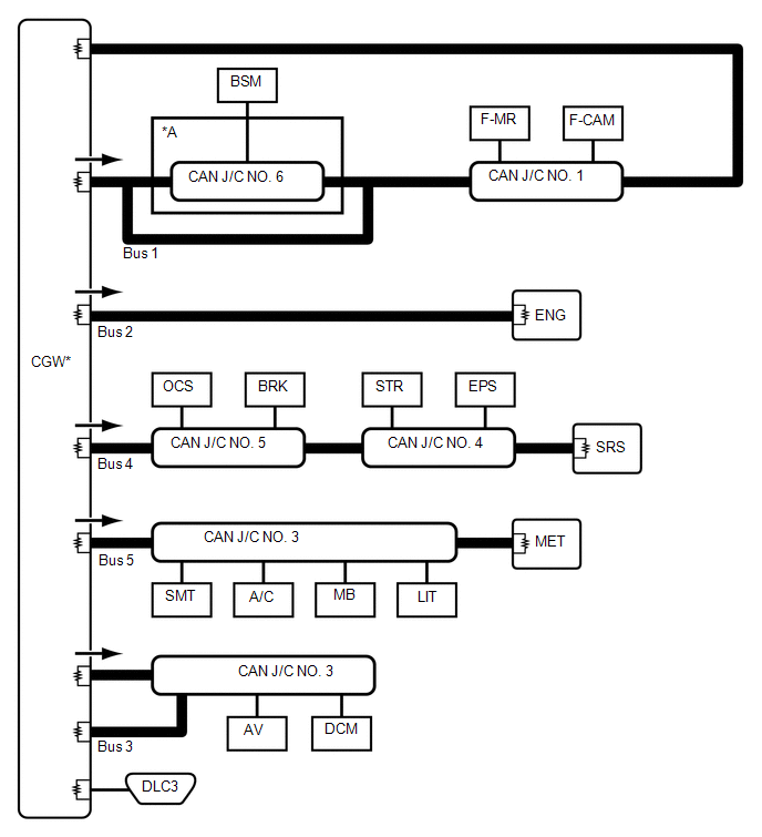
*A |
with blind spot monitor system |
- |
- |
 |
CAN Main Bus Line |
 |
Terminating Resistor |
 |
CAN Branch Line |
* |
ECU with Gateway Function |
 |
Bus Check Direction |
- |
- |
Connects to | Code | ECU / Sensor Name | CAN DTC Storage | Note |
|---|---|---|---|---|
- |
CGW |
Central Gateway ECU (Network Gateway ECU) |
- |
- |
- |
DLC3 |
DLC3 |
- |
- |
Bus 1 |
BSM |
Left blind spot monitor sensor |
Available |
with blind spot monitor system |
F-CAM |
Front Area Recognition Camera |
Available |
with Toyota Safety Sense P system |
|
F-MR |
Millimeter Wave Radar Sensor Assembly |
Available |
with Toyota Safety Sense P system |
|
CAN J/C No. 6 |
CAN J/C Connector No. 6 |
- |
with blind spot monitor system |
|
CAN J/C No. 1 |
CAN J/C Connector No. 1 |
- |
- |
|
Bus 2 |
ENG |
ECM |
Available |
- |
Bus 3 |
Front |
Radio and Display Receiver Assembly |
Available |
for radio and display type |
DCM |
DCM (Telematics Transceiver) |
Available |
with telematics transceiver |
|
CAN J/C No. 3 |
Junction Connector No. 3 |
- |
- |
|
Bus 4 |
STR |
Steering angle sensor |
- |
- |
EPS |
Power steering ECU assembly |
Available |
- |
|
BRK |
Brake Actuator Assembly |
Available |
- |
|
OCS |
Occupant Detection ECU |
Available |
with occupant detection ECU |
|
SRS |
Airbag sensor assembly |
Available |
- |
|
CAN J/C No. 5 |
CAN Junction Connector No. 5 |
- |
- |
|
CAN J/C No. 4 |
CAN Junction Connector No. 4 |
- |
- |
|
Bus 5 |
d'A/C |
Air Conditioning Amplifier Assembly |
Available |
Connected to LIN communication system |
SMT |
Certification ECU (Smart Key ECU Assy) |
Available |
with Smart Key System |
|
MB |
Main body ECU (multiplex network body ECU) |
Available |
Connected to LIN communication system |
|
LIT |
LH HEADLIGHT ECU SUB-ASSEMBLY |
Available |
for LED headlight |
|
MET |
Combination meter assembly |
Available |
- |
|
CAN J/C No. 3 |
CAN Junction Connector No. 3 |
- |
- |