How to Use Troubleshooting
PRECAUTION / NOTICE / HINT
PRECAUTIONS TO FOLLOW WHEN TROUBLESHOOTING
NOTICE:
- Because the diagnostic sequence is important for accurate diagnosis, be sure to perform troubleshooting using the section "How to Use Troubleshooting" when CAN communication system DTCs are output.
- If the CAN communication system malfunctions, check the terminal contact pressure of the connectors, as insufficient terminal contact pressure may be the cause.
Click here

- Before measuring the CAN bus resistance, turn the ignition switch OFF and leave the vehicle for at least 1 minute without using the key or switches, and without opening or closing any doors. Then disconnect the cable from the negative (-) battery terminal and leave the vehicle for at least 1 minute before measuring the resistance.
- After turning the ignition switch OFF, a waiting time may be required before disconnecting the cable from the negative (-) battery terminal. Therefore, be sure to read the precautions for disconnecting the cable from the negative (-) battery terminal before performing the work.
Click here
(a) CAN communication DTCs are output for malfunctions of the CAN sub-bus and CAN main bus, as well as for internal malfunctions or power source malfunctions of the ECUs or sensors that use CAN communication. Therefore, if DTCs for internal malfunctions or power source malfunctions of the relevant systems are output at the same time as CAN communication DTCs, troubleshoot according to the internal malfunction and power source DTCs.
(b) The DLC3 check can only be used to detect malfunctions in the diagnostic bus (the bus that connects the DLC3 to the central gateway ECU (network gateway ECU)).
(c) Open circuits in the sub-bus of sensors or ECUs connected to the CAN main bus can be checked by inspecting the CAN bus using the Techstream. (This check can be performed when all main bus lines are operating normally.)
(d) If there is a communication error history in the central bus, identify the ECUs or sensors that are not communicating by analyzing the combination of recorded DTCs or by performing the Bus Communication Check (Detail).
(e) If a sub-bus has a communication error, the ECU equipped with the gateway function (sub-bus control ECU) detects it and records the DTCs related to the error.
HINT:
On the Techstream, ECUs equipped with the gateway function display the DTCs of the ECUs connected to the sub-bus.
(f) When an open circuit is detected, before disconnecting the related connectors for inspection, push on the connector to make sure it is not loose or disconnected.
(g) When disconnecting a connector, make sure the terminals and connector body are not cracked, deformed, or corroded.
PROCEDURE
VEHICLE BROUGHT TO WORKSHOP
HINT:
- If the ignition switch can be turned ON (power source mode can be set to ON) when the vehicle is brought in for repair, check whether DTCs are output, and quickly check the illumination status of all warning lights on the instrument cluster and the basic vehicle operation (such as steering operation).
- Do not turn the ignition switch OFF until vehicle inspection is complete, as some fail-safe functions are cancelled when the ignition switch is turned OFF.
- If the ignition switch cannot be turned ON (power source mode cannot be set to ON) when the vehicle is brought in, measure the battery voltage. If the voltage is below 11 V, charge or replace the battery before troubleshooting.
- If the ignition switch cannot be turned ON (power source mode cannot be set to ON) even though the battery voltage is normal, repair this malfunction before troubleshooting.
Click here
|

CUSTOMER PROBLEM ANALYSIS
HINT:
- When troubleshooting, make sure the symptoms of the problem have been correctly identified. Any preconceptions must be set aside in order to make an accurate judgment. To clearly understand the actual symptoms of the problem, it is essential to ask the customer about the nature of the problem and the conditions under which it occurred.
- Ask the customer whether the vehicle is or was equipped with aftermarket devices, such as an anti-theft device or system. (If so, explain to the customer that the aftermarket devices will be removed before troubleshooting, as they may interfere with correct malfunction verification.)
- Examples of items to confirm are shown below.
(a) It is useful to check the symptoms and the conditions under which the vehicle was operating when the malfunction occurred. This helps identify the defective part.
HINT:
- What was affected (system, part, or instrument cluster warning light)
- What happened (malfunction information)
- Date (date and time of occurrence, frequency, and whether it recurs or not)
- What kind of situation the problem occurred in (driving and operating conditions at the time of occurrence, and weather conditions)
- Road type or condition (city, suburb, paved road, unpaved road, highway, etc.)
- Conditions under which the symptom returned to normal (what caused the vehicle to return to normal, for example, the ignition switch was turned OFF)
Symptom |
|
Instrument Cluster Warning Lights |
|
|
PRELIMINARY CHECKS
(a) Measure the battery voltage with the ignition switch OFF.
Standard voltage:
11 à 14 V
If the voltage is below 11 V, charge or replace the battery before proceeding to the next step.
HINT:
- It is possible to check whether the battery is completely discharged by operating the horn.
- If the ignition switch cannot be turned to the ON position, measure the battery voltage. If it is less than 11 V, perform the check after replacing or charging the battery.
- If the ignition switch cannot be turned to the ON position even though the battery voltage is normal, repair the malfunction before proceeding with troubleshooting.
Click here
| NG |  |
CHARGE OR REPLACE BATTERY |
|
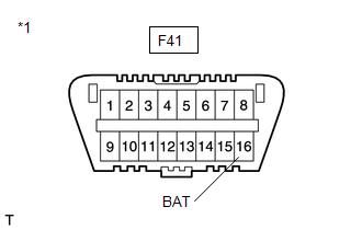
CHECK WIRE HARNESS AND CONNECTOR (BAT - BODY GROUND)
(a) Measure the voltage according to the value(s) shown in the table below. Standard voltage:
|
|
| NG | |
REPAIR OR REPLACE HARNESS OR CONNECTOR |
|
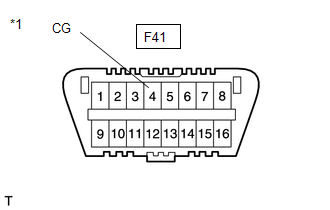
CHECK WIRE HARNESS AND CONNECTOR (CG - BODY GROUND)
(a) Measure the resistance according to the value(s) in the table below. Standard resistance:
|
|
| NG | |
REPAIR OR REPLACE HARNESS OR CONNECTOR |
|
CHECK TECHSTREAM OPERATION
HINT:
Read the Techstream operator's manual carefully before use.
Click here
(a) Connect the Techstream to the DLC3.
(b) Turn the ignition switch to ON.
(c) Turn on the Techstream.
(d) Make sure that the Techstream and the ECUs can communicate when the ignition switch is in the ON position.
HINT:
- The ECUs and sensors are not displayed on the "Communication Bus Check" screen when the Techstream cannot communicate with the vehicle.
- If communication between the Techstream and the ECUs is not possible, the vehicle or the Techstream has a malfunction.
- If communication between the ECUs and the Techstream still cannot be established, even when the Techstream is connected to another vehicle, the Techstream has a malfunction. Perform the tests described in the Techstream operator's manual. (The Techstream may be malfunctioning or the battery may be discharged.)
Result:
Result | Proceed to |
|---|---|
OK (Communication between the Techstream and the vehicle is possible.) |
A |
OK (Communication between the Techstream and the vehicle is not possible, but it is possible when the Techstream is connected to another vehicle). |
B |
NG (Communication is not possible between the Techstream and the vehicle, nor between the Techstream and another vehicle.) |
C |
| B | |
GO TO STEP 15 |
| C | |
REFER TO TECHSTREAM OPERATOR'S MANUAL |
|
CHECK DTC (HEALTH CHECK)
(a) Using the Techstream, perform the status check to read the current and past DTCs, and record them.
NOTICE:
- CAN communication DTCs are output when there is an open or short circuit in one of the communication lines. These DTCs are also output when there is a problem with the power supply of an ECU or the corresponding sensor, or a problem with the ECU or sensor itself.
- If a CAN communication line connector is disconnected while the ignition switch is in the ON or ACC position, the ECUs of the corresponding system and related systems record a DTC.
HINT:
If an open circuit occurs in only one of the CAN sub-bus lines, DTCs unrelated to the defective parts may be output (DTCs may be displayed at random) or a message indicating a communication error may be displayed.
(b) Using the Techstream, retrieve the freeze frame data and record it.
Result:
Result | Proceed to |
|---|---|
OK (only CAN communication DTCs are output). |
A |
NG (DTCs other than CAN communication DTCs are output). |
B |
| B | |
GO TO DTC CHART FOR THE APPLICABLE SYSTEM |
|
CHECK WHETHER DTCS ARE OUTPUT (IDENTIFY THE BUS WITH THE MALFUNCTION)
(a) Switch from the "Communication Bus Check" screen to the "Communication Malfunction Check" screen.
(b) Record all DTCs stored for the ECUs and sensors.
(c) Check whether the stored DTCs are listed in the CAN communication DTC chart.
HINT:
- For details on how to enter and exit the "Communication Malfunction Check" screen, refer to the communication bus check (Communication Malfunction Check).
Click here
- For the definitions of central bus, sub-bus and local bus, refer to the terms definitions.
Click here
- A sub-bus control ECU is an ECU equipped with a gateway function that controls the ECUs and sensors on its corresponding bus.
- When the vehicle is equipped with a sub-bus, refer to the system diagram to check the sub-bus control ECU.
Click here
- Sub-bus control ECUs monitor all ECUs and sensors connected to their respective sub-buses and can accurately detect when an ECU or sensor stops communicating.
- When CAN communication DTCs are stored but all ECUs and sensors connected to the CAN communication system are displayed as normal on the Techstream "Communication Bus Check" screen, a past malfunction is suspected.
- When a secondary bus control ECU detects a communication error in the network, such as an ECU or sensor that has stopped communicating, it records a DTC.
- When CAN communication DTCs are recorded in an ECU connected to the central bus control ECU and secondary bus control ECU, check the corresponding secondary bus and make repairs if necessary before checking the central bus.
- A malfunctioning local bus will not affect the central bus or secondary buses.
- When CAN communication DTCs are recorded for a local bus, check the corresponding systems and make necessary repairs.
Result:
Result | Proceed to |
|---|---|
Stored DTCs are not listed in the diagnostic trouble code chart for the CAN communication system. |
A |
Stored DTCs are listed in the diagnostic trouble code chart for the CAN communication system. |
B |
| B | |
GO TO DIAGNOSTIC TROUBLE CODE CHART |
|
BUS CHECK (CHECK ECUs AND SENSORS CONNECTED USING TECHSTREAM)
(a) Depending on the vehicle equipment and specifications, check the systems that use CAN communication.
Click here
(b) Select "CAN Bus Check" on the Techstream screen.
(c) Observe the screen for approximately 2 minutes to check the ECUs and sensors displayed on the screen.
(d) Check the ECUs or sensors using the background color, which indicates that they are not currently communicating.
NOTICE:
- A secondary bus control ECU outputs DTCs for its respective ECUs and sensors. Identify the malfunctioning ECU or sensor using the output DTCs.
- ECUs or sensors that are not installed on the vehicle are not displayed. Do not confuse ECUs or sensors that are not installed with ECUs or sensors that are not communicating.
- When using the combined area, it may be possible to select a secondary bus (in the drop-down list) that has no ECUs or sensors connected. This is not a malfunction. It occurs when no optional device is connected to a secondary bus monitored by a secondary bus control ECU (ECU equipped with the gateway function).
HINT:
- For more information on how to read the "Communication Bus Check" screen, refer to the description of the "Communication Bus Check" screen.
Click here
- If an ECU or sensor whose connection status changes intermittently is displayed on the "Communication Bus Check" screen, there may be an open circuit in one of the wires of a secondary line of an ECU or sensor on the bus. If an open occurs in one of the wires of a CAN secondary line, it may interfere with communication with other ECUs or sensors, causing an incorrect status to be displayed.
- The central gateway ECU (network gateway ECU) displays on the Techstream the connection status of the ECUs and sensors connected to the central bus.
- The secondary bus control ECUs display on the Techstream the connection status of the ECUs and sensors connected to their respective secondary buses.
- If a CAN switching DTC is output for an ECU connected to the secondary bus, refer to the corresponding diagnostic procedure.
Click here
Result:
Result | Proceed to |
|---|---|
An ECU or sensor is not communicating (an ECU or sensor shows a red or red and yellow background) |
A |
All ECUs and sensors are communicating (All ECUs and sensors show a white or white and yellow background) |
B |
| B | |
GO TO STEP 12 |
|
CHECK PROBLEM SYMPTOMS (CHECK ECUs AND SENSORS CONNECTED USING TECHSTREAM)
(a) Check the possible cause of the problem symptoms by referring to the "How to Use the Communication Bus Check Screen" section during inspection and using the bus check result (check ECUs and sensors connected using Techstream).
HINT:
- For details on how to check the buses, refer to the "How to Use the Communication Bus Check Screen" section during inspection.
Click here
- If multiple ECUs or sensors are not communicating, check for blown fuses before troubleshooting.
- If multiple ECUs or sensors are not communicating, after confirming there is no power supply malfunction, check for open circuits in the CAN bus main lines, short circuits in the CAN bus lines (CANH or CANL), or short circuits to ground or +B in the CAN bus lines.
- If an ECU or sensor that is not communicating is detected, there may be an open circuit in one of the wires of its secondary line. In this case, the malfunctioning wire harness may affect noise immunity with communication of other ECUs or sensors on the same bus. This may affect the validity of the displayed data.
Result:
Result | Proceed to |
|---|---|
The problem symptom is found in the table of problem symptom examples other than A or B. |
A |
|
B |
| A | |
REFER TO SYMPTOM TROUBLESHOOTING TABLE |
|
CAN BUS CHECK (DETERMINE CAUSE OF PROBLEM SYMPTOMS)
(a) Disconnect the cable from the negative (-) battery terminal.
(b) Measure the resistance of the suspect buses identified by the problem symptom confirmation result (check ECUs and sensors connected using Techstream).
HINT:
- For details on the terminal layout of the central gateway ECU (network gateway ECU), refer to the ECU terminals.
Click here
- If the main CAN bus lines operate normally and an ECU or sensor whose connection status changes intermittently when checking the "Communication Bus Check" screen, there may be an open circuit in one of the wires of a branch line of an ECU or sensor on the bus. If an open occurs in one of the wires of a CAN branch line, it may interfere with communication of other ECUs or sensors, causing an incorrect status to be displayed.
Performing the bus check again may help identify the affected component.
Standard resistance:
Tester Connection | Condition | Specified Condition | Result |
|---|---|---|---|
CANH - CANL of a suspected bus |
Cable disconnected from negative (-) battery terminal |
54 à 69 Ω |
Below 54 Ω: Short circuit between bus lines |
70 Ω or higher: Open circuit in CAN main bus lines |
|||
CANH - Body ground of a suspected bus |
Cable disconnected from negative (-) battery terminal |
200 Ω or higher |
Below 200 Ω: CANH short to ground |
CANL - Body ground of a suspected bus |
Cable disconnected from negative (-) battery terminal |
200 Ω or higher |
Below 200 Ω: CANL short to ground |
CANH - +B of a suspected bus |
Cable disconnected from negative (-) battery terminal |
6 kΩ or higher |
Below 6 kΩ: CANH short to +B |
CANL - +B of a suspected bus |
Cable disconnected from negative (-) battery terminal |
6 kΩ or higher |
Below 6 kΩ: CANL short to +B |
Result:
Result | Proceed to |
|---|---|
OK (main CAN bus lines operate normally) |
Refer to the Check for Open Circuit in Branch Line section |
NG (there is an open or short circuit in a CAN bus line of a suspected bus) |
Refer to the applicable check |
| Refer to the Check for Open Circuit in Branch Line section | |
REFER TO SYMPTOM TROUBLESHOOTING TABLE |
| Refer to the applicable check | |
REFER TO SYMPTOM TROUBLESHOOTING TABLE |
BUS CHECK (DETAIL) (CHECK ECUS AND SENSORS CONNECTED USING TECHSTREAM)
(a) Using Techstream, display the "Communication Bus Check (Detail)" screen.
HINT:
For details on how to check the buses using the "Communication Bus Check (Detail)" screen, refer to the description of the "Communication Bus Check" screen.
Click here
(b) Check the display of ECUs or sensors that have a communication error history.
NOTICE:
- ECUs or sensors that are not installed on the vehicle are not displayed. Do not confuse ECUs or sensors that are not installed with ECUs or sensors that are not communicating.
- When using the combined area, it may be possible to select a secondary bus (in the drop-down list) that has no ECUs or sensors connected. This is not a malfunction. It occurs when no optional device is connected to a secondary bus monitored by a secondary bus control ECU (ECU equipped with the gateway function).
HINT:
- The communication history of ECUs or sensors with a communication error history can be displayed on the "Communication Bus Check (Detail)" screen.
- Lost Communication Time and Lost Communication Trip are displayed only for the central bus.
- Lost Communication Time and Lost Communication Trip are not displayed for branch buses.
(c) Check ECUs or sensors with a red background.
Result:
Result | Proceed to |
|---|---|
An ECU or sensor has a communication stop history. (the background color of an ECU or sensor is red.) |
A |
No ECU or sensor has a communication stop history. (the background color of an ECU or sensor is not red.) |
B |
| B | |
GO TO STEP 14 |
|
CHECK PROBLEM SYMPTOMS (CHECK ECUs AND SENSORS CONNECTED USING TECHSTREAM)
(a) Check the possible cause of the problem symptoms by referring to the section How to Use the "Communication Bus Check (Detail)" Screen during Inspection, and using the bus check (detail) result (check ECUs and sensors connected using Techstream).
NOTICE:
- ECUs or sensors that are not installed on the vehicle are not displayed. Do not confuse ECUs or sensors that are not installed with ECUs or sensors that are not communicating.
- When using the combined area, it may be possible to select a secondary bus (in the drop-down list) that has no ECUs or sensors connected. This is not a malfunction. It occurs when no optional device is connected to a secondary bus monitored by a secondary bus control ECU (ECU equipped with the gateway function).
HINT:
- For details on the "Communication Bus Check (Detail)" screen, refer to How to Use the "Communication Bus Check (Detail)" Screen during Inspection.
Click here
- Lost Communication Time and Lost Communication Trip are displayed only for the central bus.
- Lost Communication Time and Lost Communication Trip are not displayed for branch buses.
- If an ECU or sensor has a communication stop history, its background color is red.
- If more than one ECU or sensor has a red background, check the Lost Communication Trip and Lost Communication Time values. A communication error of the ECU or sensor with the Lost Communication Trip value closest to the Current Trip value and the largest Lost Communication value is suspected.
Result:
Result | Proceed to |
|---|---|
The suspected cause of the system problem is identified. |
A |
The suspected cause of the system problem is not identified. |
B |
| A | |
REFER TO SYMPTOM TROUBLESHOOTING TABLE |
|
CHECK DTC COMBINATION TABLE
(a) Confirm the problem according to the DTC combination output for the CAN communication system.
Click here
Result:
Result | Proceed to |
|---|---|
The DTC combination is not in the DTC combination table. |
A |
The DTC combination is in the DTC combination table. |
B |
| A | |
CHECK FOR INTERMITTENT PROBLEMS |
| B | |
CHECK PROBLEMS ACCORDING TO DTC COMBINATION TABLE |
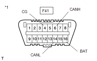
CHECK WIRE HARNESS AND CONNECTOR (DLC3 - CENTRAL GATEWAY ECU (NETWORK GATEWAY ECU))
NOTICE:
Before measuring the CAN bus resistance, turn the ignition switch OFF and leave the vehicle for at least 1 minute without using the key or switches, and without opening or closing any doors. Then disconnect the cable from the negative (-) battery terminal and leave the vehicle for at least 1 minute before measuring the resistance.
HINT:
Operating the ignition switch, any other switch or a door triggers CAN communication from the corresponding ECU or sensor. This communication changes the resistance value.
(a) Disconnect the cable from the negative (-) battery terminal.
(b) Measure the resistance according to the value(s) in the table below. Standard resistance:
HINT: If the resistance between CANH and CANL is not as specified, a connector may have been loose or disconnected during inspection. If a connector is loose or disconnected, reconnect it and perform the check again. |
|
| NG | |
REPAIR OR REPLACE WIRE HARNESS OR CONNECTOR (DLC3 - CENTRAL GATEWAY ECU (NETWORK GATEWAY ECU)) |
|
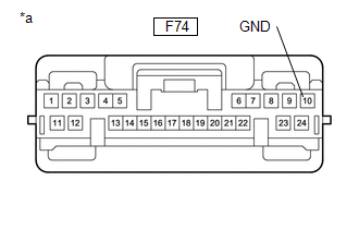
CHECK WIRE HARNESS AND CONNECTOR (GROUND CIRCUIT)
(a) Disconnect the central gateway ECU (network gateway ECU) connector.
(b) Measure the resistance according to the value(s) in the table below. Standard resistance:
|
|
| NG | |
REPAIR OR REPLACE WIRE HARNESS OR CONNECTOR (GND TERMINAL) |
|
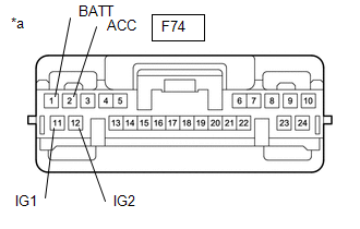
CHECK HARNESS AND CONNECTOR (POWER SOURCE CIRCUIT)
(a) Reconnect the cable to the negative (-) battery terminal.
(b) Measure the voltage according to the value(s) in the table below. Standard voltage:
|
|
| OK | |
REPLACE CENTRAL GATEWAY ECU (NETWORK GATEWAY ECU) |
| NG | |
REPAIR OR REPLACE WIRE HARNESS OR CONNECTOR (POWER SOURCE CIRCUIT) |