Navigation
Vehicle Speed Signal Circuit between Radio and Navigation Assembly and Combination Meter
In this manual: Navigation
10steps
~60min
3/5difficulty
Done 0 of 10
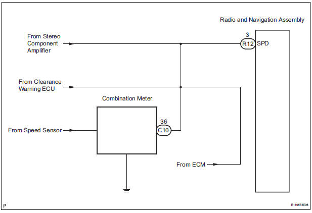
DESCRIPTION The radio and navigation assembly receives a vehicle speed signal from the combination meter and information about the GPS antenna, and then adjusts vehicle position.
HINT:
- A voltage of 12 V or 5 V is output from each ECU and then input to the combination meter. The signal is changed to a pulse signal at the transistor in the combination meter. Each ECU controls the respective system based on the pulse signal.
- If a short occurs in an ECU, all systems in the diagram below will not operate normally.
WIRING DIAGRAM
INSPECTION PROCEDURE
1 CHECK OPERATION OF SPEEDOMETER
- Drive the vehicle and check if the function of the speedometer on the combination meter is normal.
OK: Actual vehicle speed and the speed indicated on the speedometer are the same
HINT: The vehicle speed sensor is functioning normally when the indication on the speedometer is normal.
2 INSPECT RADIO AND NAVIGATION ASSEMBLY
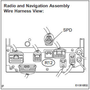
- Disconnect the radio and navigation assembly connector R12.
- Measure the voltage.
- Jack up either one of the drive wheels.
- Move the shift lever to the neutral position.
- Turn the ignition switch to the ON position
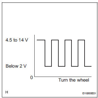
- Measure the voltage between terminal SPD of the radio and navigation assembly and body ground when the drive wheels are turned slowly.
OK: Voltage pulses as shown in the illustration.
3 CHECK HARNESS AND CONNECTOR (COMBINATION METER - RADIO AND NAVIGATION ASSEMBLY)
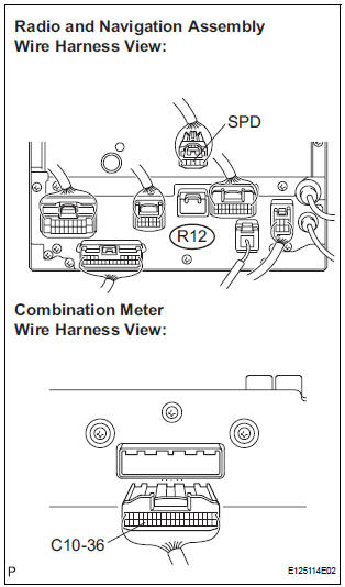
- Disconnect the radio and navigation assembly connector R12 and combination meter connector C10.
- Measure the resistance according to the value(s) in the table below.
Standard resistance

4 CHECK HARNESS AND CONNECTOR (COMBINATION METER - RADIO AND NAVIGATION ASSEMBLY)
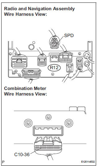
- Disconnect the radio and navigation assembly connector R12 and combination meter connector C10.
- Measure the resistance according to the value(s) in the table below.
Standard resistance

HINT: If the resistance between terminal SPD and body ground is less than 10 kΩ, there may be a short in a wire harness, connector, or an ECU.
REPLACE COMBINATION METER
Test yourself
A quick Toyota Sienna quiz: every answer comes with an explanation and a link to the manual page.
Was this page helpful?