Front Suspension Repair
Many front suspension components can be removed and reinstalled independently. However, certain tasks still require workshop equipment. Damaged suspension parts must never be straightened or, especially, welded; they must always be replaced with new ones.
Removing the Front Strut
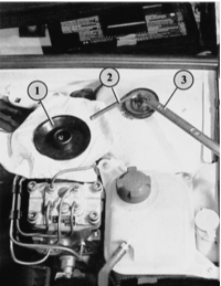
Removing the strut at the top. After removing the cover (1), the strut mounting nut can be loosened using a open-end wrench (3). To do this, hold the shock absorber piston rod with a hex key (2).

Removing the strut at the bottom. Shown are the bolted connections of the stabilizer bar link (1) and the bolted connections to the wheel hub bearing housing (2 and 3).
When removing the strut, note the following: if it is disconnected from the wheel hub bearing housing, wheel alignment angles must be readjusted, which can only be done on an alignment bench in a workshop.
For this reason, the strut is described here for removal together with the wheel hub bearing housing.
Additional note: workshop mechanics use hex socket VW 3078 to tighten the upper strut nut. If this tool is not available, an open-end wrench and experience may be used instead.
PROCEDURE
Obtain a new self-locking nut and a new clamp bolt for the independent suspension joint.
With the vehicle standing on its wheels, loosen the center bolt of the drive axle shaft in the wheel hub (at the center of the wheel).
Loosen the wheel bolts.
Raise the front of the vehicle evenly so that the stabilizer bar is not loaded. Secure the vehicle.
Remove the wheel.
Disconnect the stabilizer bar link from both strut assemblies. Press the stabilizer bar upward.
Remove the brake caliper bracket and secure it to the body with wire. The brake line remains connected.
Disconnect the tie rod end ball joint.
Remove the pinch bolt of the lower ball joint at the bottom of the strut assembly.
Using a pry bar, pull the ball joint stud out of the strut assembly. This separates the strut assembly from the control arm. Do not widen the slot in the wheel bearing housing, for example with a screwdriver.
Turn the steering wheel out and remove the drive axle shaft from the wheel hub.
Remove the cover from the strut tower in the engine compartment.
Remove the strut mount nut at the top of the piston rod. Hold the piston rod with an Allen key.
Hold the strut assembly from below while doing this.
Lower the strut assembly downward and remove it completely from the drive axle shaft.
For installation, use new self-locking nuts and a new ball joint pinch bolt.
Install the pinch bolt so that its head faces forward in the direction of travel.
Tightening torques: strut upper mount nut: 60 N·m; tie rod end nut: 30 N·m; control arm ball joint pinch bolt: 50 N·m; stabilizer bar link to strut: 40 N·m.
If the same strut assembly is installed and the bolts connecting the wheel bearing housing and the strut remain clamped throughout, wheel alignment adjustment is not required.
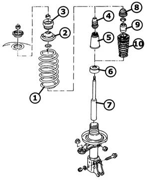
Front strut components and installation sequence
1 – spring;
2 – spring plate;
3 – strut mount bearing;
4 – bump stop;
5 – protective boot;
6 – threaded cap;
7 – shock absorber;
8 – 10 – spacer, boot.
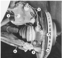
Audi 80 front wheel suspension, close-up
1 – strut housing;
2 – bolted connections of strut housing and wheel bearing housing;
3 – wheel bearing housing;
4 – ball joint;
5 – pinch bolt;
6 – lower control arm.
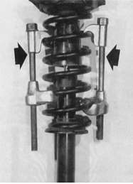

Left: spring compressors are required to separate the spring from the shock absorber when the strut assembly is removed.
Right: the illustration shows the ball joint pinch bolt (1), which secures the ball joint (3) in the wheel bearing housing. Also shown are the retaining nuts (2) connecting the ball joint to the lower control arm.
Test yourself
A quick Audi 80 quiz: every answer comes with an explanation and a link to the manual page.