Brake System Inspection
* Dust generated by brake pad wear and accumulating on brake components may contain asbestos, which is harmful to health. Do not blow this dust off with compressed air and do not breathe it in! Do not use gasoline-based solvents to remove dust. Dust should be washed off with a special brake system cleaner or methyl alcohol into a drain container. After wiping brake components with a damp cloth, keep this cloth and the contents of the drain container in a closed and labeled container. In the future, whenever possible, use asbestos-free components.
* In addition to inspections at specified intervals, check the condition of the brake units each time the wheels are removed or when signs of malfunction appear. For driving safety, the brake system inspection procedures described below are the most important of all vehicle maintenance procedures you perform.
Brake System Malfunction Symptoms
Disc brake units have built-in friction pad wear indicators that signal when pad wear has reached the critical limit. In this case, the pads must be replaced immediately, otherwise the brake discs will be damaged and will require costly repair.
Any of the symptoms listed below may indicate a potential brake system defect:
a) The vehicle pulls to one side when the brake pedal is depressed
b) The brake units make scraping or squealing noises when braking
c) The brake pedal has excessive travel
d) The brake pedal pulsates (this is normal only when the ABS is operating)
e) Brake fluid leaks are present (usually on the inside of the tire or wheel)
If at least one of these symptoms is detected, inspect the brake system immediately.
Brake Lines and Hoses
The brake system mainly uses steel brake pipes, except for flexible reinforced hoses at the front wheels and as connections at the rear axle. Regular inspection of all these lines is very important.
PROCEDURE
1. Park the vehicle on level ground and turn off the engine. Remove the wheel covers. Loosen, but do not remove, the wheel bolts on all four wheels.
2. Raise the rear of the vehicle and securely support it on stands.
3. Remove the wheels (refer to the sections "Jacking and Towing" or "Controls and Safe Operating Practices").
4. Clean the lines with brake line cleaner.
* Corrosion-protection brake lines have a plastic coating. If the coating is damaged, the line may corrode. For this reason, do not clean brake lines with a wire brush, sandpaper, or screwdriver.
5. Use a light to inspect the brake lines running from the master cylinder to the ABS unit and from it to the individual wheel cylinders. The master cylinder is located under the brake fluid reservoir.
6. Do not kink or crush the lines. Also make sure there is no corrosion damage or chafing. If any of these defects are found, replace the line in that section.
7. Brake hoses connect the lines to the moving components of the brake system. They are made of high-strength material, but over time they may develop porosity, swelling, and damage from sharp objects. If any of these defects are found, replace the hoses immediately with new ones.
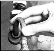
8. Bend the brake hoses by hand in different directions to check for damage. Do not twist the hoses. Make sure the colored lines on the hoses are straight, if present!
9. Turn the steering wheel fully to the right and to the left. The hoses must not contact any body or suspension components.
10. The hose connections and lines must show no signs of leakage.
11. Lower the vehicle onto its wheels.
Disc Brake Units
When the brake pads of the front and rear brakes reach a specified wear level, the warning indicator on the instrument panel illuminates. In this case, the brake pads must be replaced immediately.
PROCEDURE
1. If not already done, raise the vehicle and securely support it on stands.
2. Mark the position of each wheel relative to the hub so that balanced wheels return to their original position after installation. Loosen the wheel bolts. Remove the wheels.
3. The disc brake calipers, containing the pads, are now visible. Each caliper contains outer and inner pads.
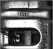
4. Visually check the pad thickness from above through the caliper.
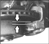
5. Check the thickness of the outer brake pad. If the thickness is approaching the wear limit, remove the pad and measure its thickness with a gauge.
6. The wear limit for front and rear brake pads is a thickness of 2 mm.
If the friction material thickness is less than specified, or if it is worn more on one side than the other, replace the pads. Note that the friction material is normally bonded to a metal backing plate; the thickness of the backing plate must not be included in the measurement. Always replace the pads on both sides of the vehicle (as a set on one axle), even if only one of them is worn, otherwise braking will be uneven.
* Experience shows that 1 mm of brake pad wear corresponds to at least 1000 km of mileage. This applies to severe operating conditions. Under normal operation, pad life is considerably longer. When the disc brake pad thickness is 5 mm (without backing plate), the pad can still be used for at least 3000 km.
7. Remove the calipers without disconnecting the brake hoses.
8. Check the condition of the brake disc. Inspect it for grooves, deep scratches and areas of overheating (they appear as blue or discolored spots). If signs of damage or wear are found, the disc can be removed and turned at a machine shop; if this is not possible, replace it. In either case, both discs must be replaced or turned, even if only one is worn.
Parking Brake Drum Mechanisms
PROCEDURE
1. Using the instructions in the Brake System section, remove the rear brake discs with drums.
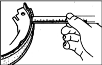
2. Measure the thickness of the friction linings on the rear brake shoes and inspect them for signs of contamination by brake fluid or grease. If the lining thickness is 1.5 mm or less above the rivet heads or the metal backing at its thinnest point, replace all shoes. Refer to the accompanying illustration. Shoes that are cracked, glazed, or contaminated with brake fluid or grease must also be replaced. For the replacement procedure, refer to the Brake System section.
3. Check the condition of the shoe return and hold-down springs, as well as the adjuster mechanism. Make sure all these components are correctly installed and in working condition. Worn or deformed springs may cause premature wear of the friction linings.
4. Check the wheel cylinders for signs of leakage by carefully pulling back the protective rubber boots. Slight traces of moisture under the boots are acceptable. If brake fluid is found under the boots or is leaking from the wheel cylinder, the cylinders must be overhauled or replaced (refer to the Brake System section).
5. Check the drums for deep scratches, grooves, cracks and overheated areas, which appear as discolored spots. If the detected defects cannot be removed with sandpaper, the drum must be turned at a workshop (refer to the Brake System section for more detailed information).
6. Following the instructions in the Brake System section, install the brake discs with drums.
7. Install the wheels, but do not lower the vehicle yet.
Parking Brake Lever Operation and Travel Check
PROCEDURE
1. The simplest and possibly most obvious way to check the parking brake is to park the vehicle on a steep slope with the brake applied and the transmission in neutral (you should be inside the vehicle during the check). If the parking brake does not hold the vehicle from rolling, adjust the parking brake as described in the Parking Brake Adjustment section.
2. Raise the rear of the vehicle and support it on stands.
3. Apply the parking brake by 5 notches. Turn the wheels by hand. A slight resistance from the brake should be felt when turning the wheels.
4. Apply the brake by 6 notches. The wheels should still turn by hand. If the brake must be applied further to create braking, adjust the brake as described in the Parking Brake Adjustment section.
5. Lower the vehicle onto its wheels.
Test yourself
A quick BMW 1 quiz: every answer comes with an explanation and a link to the manual page.