Camshaft: Removal, Inspection and Installation
REMOVAL AND INSPECTION
PROCEDURE
1. Remove the cylinder head cover (refer to Cylinder Head Cover Removal and Installation).
2. Set the No. 1 piston to top dead center (TDC) (refer to Setting No. 1 Piston to Top Dead Center (TDC)).
3. Remove the distributor (refer to Engine Electrical section).
4. Remove the timing belt and balance shaft drive belt (refer to Rocker Arm Assembly Removal, Inspection and Installation and Camshaft Removal, Inspection and Installation).
5. If necessary, remove the camshaft sprocket bolt to separate the sprocket from the shaft journal.
To prevent the shaft from rotating, insert a screwdriver through one of the holes in the sprocket.
6. Remove the rocker arm assembly (refer to Rocker Arm Assembly Removal and Installation). If the camshaft bearing caps must be removed from the assembly, mark them in installation order (mark them asymmetrically to ensure the caps are installed in the correct position).
7. Check the camshaft end play as follows:
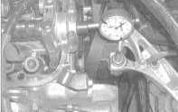
a) Install the camshaft in the engine and secure it with the bearing caps (rocker arm assembly removed);
b) Mount the dial indicator on the cylinder head with its plunger resting against the end of the shaft;
c) Using a large screwdriver as a lever, push the shaft fully rearward and zero the indicator, then push the shaft forward and read the indicator;
d) Compare the measurement with the Specifications;
e) Excessive end play indicates wear of the camshaft or cylinder head.
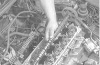
8. Remove the camshaft, wipe it dry with a clean lint-free rag or paper towel, and transfer it to a workbench.
9. To check the runout (it is recommended that this check be performed by an automotive service specialist):
a) Place the removed camshaft on two V-blocks, then press the dial indicator plunger against the center bearing journal and measure the runout while rotating the shaft;
b) Compare the measurement results with the Specifications;
c) If runout is excessive, replace the camshaft.
10. Inspect the camshaft bearing journals and the inner surfaces of the bearing caps for scratches and scoring. If serious defects are found, replace the cylinder head with a new or reconditioned unit. Using Plastigage, measure the oil clearance in each bearing. Compare the results with the Specifications. If the clearance of any bearing is outside the permissible range, replace the camshaft and/or cylinder head.
For Plastigage instructions, refer to Crankshaft Installation and Main Bearing Oil Clearance Check and Piston and Connecting Rod Assembly Installation and Connecting Rod Bearing Oil Clearance Check.
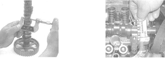
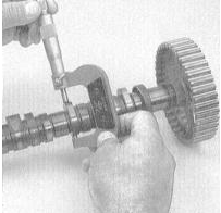
11. Evaluate the wear of the camshaft lobes:
a) Carefully inspect the working surfaces of all cam lobes for scratches, scoring, pitting, and signs of uneven wear;
b) If any lobe is defective, replace the camshaft. Determine the cause of wear: check the engine oil for abrasive particles, check the condition of the oil pump, and check the patency of all oil passages (cam lobe wear is most often caused by contaminated oil or insufficient oil supply);
c) Measure the cam lobe height with a micrometer. Compare the results with the Specifications and replace the camshaft if necessary.
12. Inspect the working surfaces of the valve rocker arms for signs of wear, scuffing, pitting, and other defects.
13. If any of the above defects are found, check the condition of the engine oil and the oil supply to the cylinder head. Only after identifying and eliminating the cause should replacement components (cylinder head, camshaft, or rocker arm assembly) be installed.
INSTALLATION
PROCEDURE
1. Thoroughly clean the camshaft, the bearing surfaces in the cylinder head and caps, and the valve rocker arms. Remove all traces of sludge and dirt. Use only clean lint-free rags to wipe the parts.
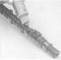
2. Lubricate the cam lobes and camshaft bearing journals with special assembly lubricant.
If the camshaft is not thoroughly lubricated before installation, serious damage to the bearings and cam lobes may occur in the first seconds after engine start-up, before normal oil circulation begins. Carefully lower the camshaft into the cylinder head (its sprocket must be positioned with the “UP” mark facing up.
3. Install the rocker arm assembly (refer to Rocker Arm Assembly Removal, Inspection and Installation).
On VTEC models, be sure to clean the oil spray nozzle jet.
4. Adjust the camshaft sprocket position so that its two side marks align with the top edge of the cylinder head. Install the timing belt and balance shaft drive belt with the associated components (refer to Balance Shaft Belt and Sprocket Removal, Inspection and Installation and Timing Belt and Camshaft Drive Removal, Inspection and Installation).
5. Install in the reverse order of removal.
Test yourself
A quick Honda Accord quiz: every answer comes with an explanation and a link to the manual page.