Rocker Arm Assembly Removal, Inspection and Installation
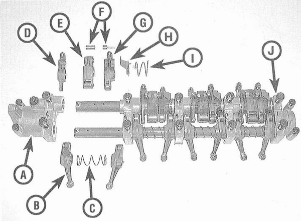
Rocker Arm Assembly Components (VTEC Models)
A — Fifth camshaft holder
B — Exhaust valve drive rocker arm (B)
C — Exhaust rocker arm shaft spring
D — Secondary intake valve drive rocker arm
E — Exhaust intermediate rocker arm
F — Pistons
G — Primary intake valve drive rocker arm
H — Distribution plate
I — Exhaust valve assembly spring
J — First camshaft holder
REMOVAL
PROCEDURE
1. Remove the cylinder head cover (refer to Cylinder Head Cover Removal and Installation).
2. Set the No. 1 piston to TDC (refer to Setting No. 1 Piston to Top Dead Center (TDC)), then remove the timing belt (refer to Timing Belt and Timing Pulley Removal, Inspection and Installation).
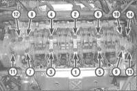
3. Loosen the camshaft bearing cap bolts by 1/4 turn (to release the force exerted by the valve springs), working in the reverse of the sequence shown in the illustration.
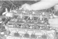
4. Remove the rocker arm shaft assembly from the cylinder head. The camshaft bearing cap bolts will keep the assembly from falling apart.
INSPECTION
PROCEDURE
1. After removing the rocker arm assembly, it is recommended to disassemble it to inspect the components more closely. Remove the mounting bolts and remove the rocker arms, springs, and bearing caps from the shafts. It is recommended to mark the position of the shafts relative to the bearing caps beforehand.
On engines equipped with VTEC, it is recommended to secure the primary and secondary intake rocker arms together with rubber bands. Keep the removed components in the order they were removed, as they must be installed in their original positions during assembly.
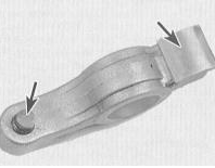
2. Thoroughly clean the components and inspect them for signs of wear and damage. Check the camshaft contact surfaces of the rocker arms. Check for scoring and signs of excessive wear on the rocker arm bore surfaces on the shafts, as well as the walls of the rocker arm bores themselves. Replace any defective components. Also make sure the oil passages inside the shafts are clear.
On VTEC models, the rocker arms are equipped with roller tips. Check the degree of wear and the freedom of rotation of the rollers.
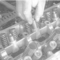
3. On engines equipped with VTEC, remove the lash adjusters from their seats in the cylinder head and clean them thoroughly. Check that the plungers move freely by hand.
INSTALLATION
PROCEDURE
1. Lubricate all components with clean engine oil and install them in their original positions on the rocker arm shafts.
Pay attention to the markings that distinguish left-side components from right-side components.
2. Lubricate the camshaft lobes and journals with special assembly lube. Apply a thin layer of anaerobic sealant to the surfaces of the No. 1 and No. 6 camshaft bearing caps that mate with the cylinder head, then install the rocker arm assembly in its original position.
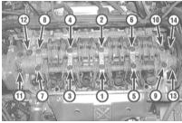
3. Tighten the camshaft cap bolts to the specified torque in the correct sequence, in several steps.
4. Install the remaining components in the reverse order of removal.
5. Finally, adjust the valve clearances if necessary (see Chapter Adjustments and Routine Maintenance).
6. Start the engine and check for oil leaks and proper operation.
Test yourself
A quick Honda Accord quiz: every answer comes with an explanation and a link to the manual page.