VTEC System - Inspection of Components
Inspection of some VTEC components requires removal of the rocker arm assembly (refer to Rocker Arm Assembly Removal, Inspection and Installation).
VTEC Lock Control Solenoid Valve
PROCEDURE
A malfunction of the VTEC solenoid valve causes a diagnostic trouble code to be stored in the self-diagnosis memory and the "Check Engine" indicator to illuminate (refer to Engine Control Section).
The most common cause of VTEC malfunction is a faulty solenoid valve or its filter. Performing regular engine oil and filter changes will help prevent such failures.
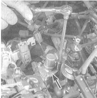
1. The VTEC lock control solenoid valve is located on the right side at the rear of the cylinder head (on the side of the rear bulkhead of the engine compartment).
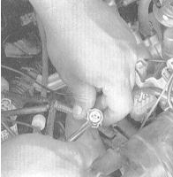
2. Check for continuity between the solenoid valve connector and body ground. Resistance should be 14 ÷ 30 Ω; if not, replace the VTEC solenoid valve.
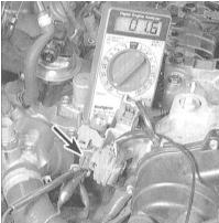
3. With the ignition off, disconnect the harness connector from the VTEC pressure switch and check continuity between the two terminals of the pressure switch on the VTEC solenoid valve. Continuity should be present; if not, replace the pressure switch.
4. Turn the ignition on and measure the voltage between the blue/black wire terminal of the pressure switch and ground. The required value is approximately 12 V; if not, check the wire between the connector and the PCM for an open circuit or short to ground.
5. With the ignition still on, measure the voltage between the terminals of the pressure switch harness connector. Voltage should be 12 V; if not, repair the open in the brown/black wire.

6. Disconnect the solenoid valve and check the plunger for free movement by hand. When installing the valve, be sure to replace the sealing gasket.
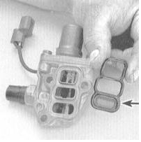
7. Completely remove the solenoid valve assembly from the cylinder head and check the condition of the sealing gasket and the passage of the filter. Clean the assembly and install it, replacing the sealing gasket beforehand.
A clogged mesh filter is the most likely cause of VTEC system malfunctions.
Rocker Arms
PROCEDURE
1. Set the No. 1 piston to TDC of the compression stroke (refer to Setting No. 1 Piston to Top Dead Center (TDC)). Remove the cylinder head cover (refer to Cylinder Head Cover Removal and Installation).
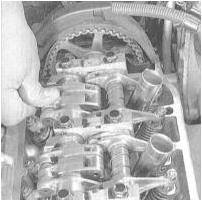
2. Press the intermediate rocker arm of the No. 1 cylinder intake valve set with your finger; it should move independently of the primary and secondary rocker arms of the assembly. Following the same procedure, check the operation of the intake valve rocker arms of the remaining cylinders (set the corresponding pistons to TDC).
Valve Lash Adjusters
PROCEDURE
1. The four lash adjuster assemblies are fitted into special bores in the engine cylinder head.
2. Remove each lash adjuster from the cylinder head individually.
3. Check the lash adjusters for proper operation by pressing the plungers with your finger. The plunger should move with slight resistance, which gradually increases as it is depressed; if not, replace the defective assembly.
Synchronizing Assemblies
PROCEDURE
1. After removing and disassembling the rocker arm assemblies (refer to Rocker Arm Assembly Removal, Inspection and Installation), also remove the synchronizing components (see below).
VTEC synchronizing assembly components:
a) Primary valve drive rocker arm (primary rocker arm);
b) Secondary valve drive rocker arm (secondary rocker arm);
c) Intermediate rocker arm;
d) Synchronizing piston A;
e) Synchronizing piston B;
f) Return piston.
2. Check the condition of the return spring. Make sure it is not broken or sagging. Replace if necessary.
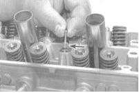
3. Check all other components (rocker arms and synchronizing pistons) for signs of wear, scuffing, scoring, overheating and other defects. Replace defective parts. Remove the oil spray jet from the third camshaft holder, clean it and reinstall it (non-VTEC engines).
4. Install in the reverse order of removal.
Assemble the components of each cylinder's assembly together, secure them with the rubber band, and only then install them on the shaft (refer to Rocker Arm Assembly Removal, Inspection and Installation).
Test yourself
A quick Honda Accord quiz: every answer comes with an explanation and a link to the manual page.