Engine Control System/Fuel System
Injector Driver Box (IDB) Circuit Diagrams
In this manual: Engine Control System/Fuel System
~6min read
IDB Terminal and Input/Output Signal

IDB Terminal Function
Connector [C110-IDB]| Pin No. | Description | Connected To |
| 1 | - | ? |
| 2 | - | ? |
| 3 | - | ? |
| 4 | - | ? |
| 5 | - | ? |
| 6 | - | ? |
| 7 | - | ? |
| 8 | - | ? |
| 9 | - | ? |
| 10 | - | ? |
| 11 | - | ? |
| 12 | - | ? |
| 13 | - | ? |
| 14 | - | ? |
| 15 | - | ? |
| 16 | Injector (Cylinder No. 3) [Low] Control Output | Injector (Cylinder #3) |
| 17 | Injector (Cylinder No. 6) [Low] Control Output | Injector (Cylinder No. 6) |
| 18 | Injector (Cylinder No. 6) [High] Control Output | Injector (Cylinder No. 6) |
| 19 | Injector (Cylinder No. 2) [Low] Control Output | Injector (Cylinder #2) |
| 20 | Injector (Cylinder No. 5) [Low] Control Output | Injector (Cylinder No. 5) |
| 21 | - | ? |
| 22 | Injector Signal Input (Cylinder No. 2) | Engine Control Module (ECM) |
| 23 | Injector Signal Input (Cylinder No. 5) | Engine Control Module (ECM) |
| 24 | - | ? |
| 25 | Fuel Pressure Regulator Valve (FPRV) Logic Input | Engine Control Module (ECM) |
| 26 | CCP-CAN [Low] | Other Control Module, Data Link Connector (DLC), Multi-Purpose Check Connector |
| 27 | CCP-CAN [High] | Other Control Module, Data Link Connector (DLC), Multi-Purpose Check Connector |
| 28 | Battery Power (B+) | Ignition Lock |
| 29 | Battery Power (B+) | Main Relay |
| 30 | Battery Power (B+) | Main Relay |
| 31 | Injector (Cylinder No. 4) [High] Control Output | Injector (Cylinder No. 4) |
| 32 | Injector (Cylinder No. 1) [High] Control Output | Injector (Cylinder No. 1) |
| 33 | Injector (Cylinder No. 3) [High] Control Output | Injector (Cylinder #3) |
| 34 | Injector (Cylinder No. 2) [High] Control Output | Injector (Cylinder #2) |
| 35 | Injector (Cylinder No. 5) [High] Control Output | Injector (Cylinder No. 5) |
| 36 | - | ? |
| 37 | - | ? |
| 38 | Injector Signal Input (Cylinder No. 3) | Engine Control Module (ECM) |
| 39 | - | ? |
| 40 | Injector Signal Input (Cylinder No. 6) | Engine Control Module (ECM) |
| 41 | Injector Signal Input (Cylinder No. 4) | Engine Control Module (ECM) |
| 42 | Battery Power (B+) | Ignition Lock |
| 43 | Battery Power (B+) | Main Relay |
| 44 | Battery Power (B+) | Main Relay |
| 45 | Fuel Pressure Regulator Valve (FPRV) [High] Control Output | Fuel Pressure Regulator Valve (FPRV) |
| 46 | Injector (Cylinder No. 4) [Low] Control Output | Injector (Cylinder No. 4) |
| 47 | Injector (Cylinder No. 1) [Low] Control Output | Injector (Cylinder No. 1) |
| 48 | ECM Ground | Ground |
| 49 | ECM Ground | Ground |
| 50 | ECM Ground | Ground |
| 51 | - | ? |
| 52 | - | ? |
| 53 | - | ? |
| 54 | - | ? |
| 55 | Injector Signal Input (Cylinder No. 1) | Engine Control Module (ECM) |
| 56 | - | ? |
| 57 | - | ? |
| 58 | - | ? |
| 59 | Battery Power (B+) | Main Relay |
| 60 | Fuel Pressure Regulator Valve (FPRV) [Low] Control Output | Fuel Pressure Regulator Valve (FPRV) |
IDB Terminal Input/Output Signal
Connector [C110-IDB]| Pin No. | Description | Condition | Type | Level |
| 1 | - | ? | ? | ? |
| 2 | - | ? | ? | ? |
| 3 | - | ? | ? | ? |
| 4 | - | ? | ? | ? |
| 5 | - | ? | ? | ? |
| 6 | - | ? | ? | ? |
| 7 | - | ? | ? | ? |
| 8 | - | ? | ? | ? |
| 9 | - | ? | ? | ? |
| 10 | - | ? | ? | ? |
| 11 | - | ? | ? | ? |
| 12 | - | ? | ? | ? |
| 13 | - | ? | ? | ? |
| 14 | - | ? | ? | ? |
| 15 | - | ? | ? | ? |
| 16 | Injector (Cylinder No. 3) [Low] Control Output | Idle | Pulse | High: Battery voltage |
| Relay ON | Low: Max. 1.0 V | |||
| 17 | Injector (Cylinder No. 6) [Low] Control Output | Idle | Pulse | High: Battery voltage |
| Relay ON | Low: Max. 1.0 V | |||
| 18 | Injector (Cylinder No. 6) [High] Control Output | Idle | Pulse | High: Battery Voltage ~ 80 V |
| Relay ON | Low: Battery Voltage | |||
| 19 | Injector (Cylinder No. 2) [Low] Control Output | Idle | Pulse | High: Battery voltage |
| Relay ON | Low: Max. 1.0 V | |||
| 20 | Injector (Cylinder No. 5) [Low] Control Output | Idle | Pulse | High: Battery voltage |
| Relay ON | Low: Max. 1.0 V | |||
| 21 | - | ? | ? | ? |
| 22 | Injector Signal Input (Cylinder No. 2) | Idle | Pulse | High: Battery voltage |
| Low: Max. 1.0 V | ||||
| 23 | Injector Signal Input (Cylinder No. 5) | Idle | Pulse | High: Battery voltage |
| Low: Max. 1.0 V | ||||
| 24 | - | ? | ? | ? |
| 25 | Fuel Pressure Regulator Valve (FPRV) Logic Input | ? | ? | ? |
| ? | ? | ? | ||
| 26 | CCP-CAN [Low] | Recessive | Pulse | 2.0 - 3.0 V |
| Dominant | 2.75 - 4.5 V | |||
| 27 | CCP-CAN [High] | Recessive | Pulse | 2.0 - 3.0 V |
| Dominant | 2.75 - 4.5 V | |||
| 28 | Battery Power (B+) | IG OFF | DC Voltage | Max. 0.5 V |
| IGNITION ON | Battery Voltage | |||
| 29 | Battery Power (B+) | IG OFF | DC Voltage | Max. 0.5 V |
| IGNITION ON | Battery Voltage | |||
| 30 | Battery Power (B+) | IG OFF | DC Voltage | Max. 0.5 V |
| IGNITION ON | Battery Voltage | |||
| 31 | Injector (Cylinder No. 4) [High] Control Output | Idle | Pulse | High: Battery Voltage ~ 80 V |
| Relay ON | Low: Battery Voltage | |||
| 32 | Injector (Cylinder No. 1) [High] Control Output | Idle | Pulse | High: Battery Voltage ~ 80 V |
| Relay ON | Low: Battery Voltage | |||
| 33 | Injector (Cylinder No. 3) [High] Control Output | Idle | Pulse | High: Battery Voltage ~ 80 V |
| Relay ON | Low: Battery Voltage | |||
| 34 | Injector (Cylinder No. 2) [High] Control Output | Idle | Pulse | High: Battery Voltage ~ 80 V |
| Relay ON | Low: Battery Voltage | |||
| 35 | Injector (Cylinder No. 5) [High] Control Output | Idle | Pulse | High: Battery Voltage ~ 80 V |
| Relay ON | Low: Battery Voltage | |||
| 36 | - | ? | ? | ? |
| 37 | - | ? | ? | ? |
| 38 | Injector Signal Input (Cylinder No. 3) | Idle | Pulse | High: Battery voltage |
| Low: Max. 1.0 V | ||||
| 39 | - | ? | ? | ? |
| 40 | Injector Signal Input (Cylinder No. 6) | Idle | Pulse | High: Battery voltage |
| Low: Max. 1.0 V | ||||
| 41 | Injector Signal Input (Cylinder No. 4) | Idle | Pulse | High: Battery voltage |
| Low: Max. 1.0 V | ||||
| 42 | Battery Power (B+) | IG OFF | DC Voltage | Max. 0.5 V |
| IGNITION ON | Battery Voltage | |||
| 43 | Battery Power (B+) | IG OFF | DC Voltage | Max. 0.5 V |
| IGNITION ON | Battery Voltage | |||
| 44 | Battery Power (B+) | IG OFF | DC Voltage | Max. 0.5 V |
| IGNITION ON | Battery Voltage | |||
| 45 | Fuel Pressure Regulator Valve (FPRV) [High] Control Output | Idle | DC Voltage | Battery Voltage |
| Max. 1.0 V | ||||
| 46 | Injector (Cylinder No. 4) [Low] Control Output | Idle | Pulse | High: Battery voltage |
| Relay ON | Low: Max. 1.0 V | |||
| 47 | Injector (Cylinder No. 1) [Low] Control Output | Idle | Pulse | High: Battery voltage |
| Relay ON | Low: Max. 1.0 V | |||
| 48 | ECM Ground | Idle | DC Voltage | Max. 50 mV |
| 49 | ECM Ground | Idle | DC Voltage | Max. 50 mV |
| 50 | ECM Ground | Idle | DC Voltage | Max. 50 mV |
| 51 | - | ? | ? | ? |
| 52 | - | ? | ? | ? |
| 53 | - | ? | ? | ? |
| 54 | - | ? | ? | ? |
| 55 | Injector Signal Input (Cylinder No. 1) | Idle | Pulse | High: Battery voltage |
| Low: Max. 1.0 V | ||||
| 56 | - | ? | ? | ? |
| 57 | - | ? | ? | ? |
| 58 | - | ? | ? | ? |
| 59 | Battery Power (B+) | IG OFF | DC Voltage | Max. 0.5 V |
| IGNITION ON | Battery Voltage | |||
| 60 | Fuel Pressure Regulator Valve (FPRV) [Low] Control Output | Idle | DC Voltage | Battery Voltage |
| Max. 1.0 V |
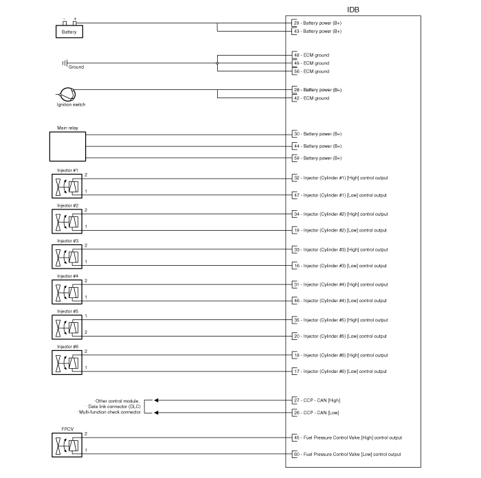
Wiring Diagram

Test yourself
A quick Hyundai Genesis DH quiz: every answer comes with an explanation and a link to the manual page.
Was this page helpful?