B2422 Back Door State
DTC DETECTION LOGIC
| DTC No. | CONSULT screen items (Trouble diagnosis content) | DTC detecting condition | |
|---|---|---|---|
| B2422–78 | BACK DOOR STATE (Back door state) |
Diagnosis condition | All times |
| Signal (terminal) | Encoder LH A signal, encoder LH B signal, encoder RH A signal, encoder RH B signal (automatic back door control module connector terminal: 19, 20, 21) | ||
| Threshold | When the automatic back door control module detect the encoder pulse signal LH does not according with the encoder pulse signal RH | ||
| Diagnosis delay time | – | ||
| B2422–79 | BACK DOOR STATE (Back door state) |
Diagnosis condition | All times |
| Signal (terminal) | – | ||
| Threshold | When automatic back door position information is deleted from automatic back door control module memory | ||
| Diagnosis delay time | – | ||
POSSIBLE CAUSE
Improper installation of back door assembly
Calibration of automatic back door position information
Back door mechanism
Encoder
Harness or connectors (encoder circuit is open or shorted)
Automatic back door control module
Battery terminal is disconnected and reconnected
FAIL-SAFE
Inhibit automatic back door system auto open/close function
PERFORM DTC CONFIRMATION PROCEDURE
 CONSULT
Ignition switch ON.
Operate automatic back door.
Select “Self Diagnostic Result” mode of “AUTO BACK DOOR”.
Is DTC detected?
YES>>DTC “B2422-78”: Refer to DTC Diagnosis Procedure (B2422-78).
YES>>DTC “B2422-79”: Refer to DTC Diagnosis Procedure (B2422-79).
NO>>To check malfunction symptom before repair: Refer to Intermittent Incident.
NO>>Confirmation after repair: Inspection End.
CHECK INSTALLATION OF BACK DOOR ASSEMBLY
Check that back door assembly is installed normally.
Refer to Adjustment.
Check back door assembly mechanism deformation, looseness, rattle, interference with other parts, and pinched foreign materials.
Is the inspection result normal?
YES>>GO TO 3.
NO>>GO TO 2.
ADJUST BACK DOOR ASSEMBLY INSTALLATION AND ERASE DTC
CONSULT
Ignition switch OFF.
Adjust the back door assembly installation. Refer to Adjustment.
Ignition switch ON.
Select “Self Diagnostic Result” mode of “AUTO BACK DOOR”.
Erase DTC, and then repeat “DTC CONFIRMATION PROCEDURE”. Refer to DTC Confirmation Procedure.
Is DTC “B2422-78” detected?
YES>>GO TO 3.
NO>>Inspection End.
CALIBRATION OF AUTOMATIC BACK DOOR POSITION INFORMATION
CONSULT
Perform initialization setting of automatic back door position information.
Refer to Work Procedure.
Erase DTC, and then repeat “DTC CONFIRMATION PROCEDURE”. Refer to DTC Confirmation Procedure.
Is DTC “B2422-78” detected?
YES>>GO TO 4.
NO>>Inspection End.
CHECK ENCODER MONITOR ITEM
CONSULT
Ignition switch ON.
Select “SPINDLE LH ENCODER A”, “SPINDLE LH ENCODER B”, “SPINDLE RH ENCODER A” and “SPINDLE RH ENCODER B” in “Data Monitor” mode of “AUTO BACK DOOR”.
Check that the function operates normally according to the following conditions:
Monitor item Condition Status SPINDLE LH ENCODER A Back door Moving (auto or manual) HI ⇔ LO When stopped HI or LO SPINDLE LH ENCODER B Moving (auto or manual) HI ⇔ LO When stopped HI or LO SPINDLE RH ENCODER A Back door Moving (auto or manual) HI ⇔ LO When stopped HI or LO SPINDLE RH ENCODER B Moving (auto or manual) HI ⇔ LO When stopped HI or LO
Is the inspection result normal?
YES>>GO TO 11.
NO>>GO TO 5.
CHECK ENCODER POWER SUPPLY
Ignition switch OFF.
Disconnect spindle unit connector.
Check voltage between spindle unit harness connector and ground.
(+) (–) Voltage
(Approx.)Spindle unit Connector Terminal LH B70 6 Ground Battery voltage RH B162
Is the inspection result normal?
YES>>GO TO 7.
NO>>GO TO 6.
CHECK ENCODER POWER SUPPLY CIRCUIT
Disconnect automatic back door control module connector.
Check continuity between automatic back door control module harness connector and spindle unit harness connector.
Automatic back door control module Spindle unit Continuity Connector Terminal Connector Terminal B55 19 LH B70 6 Yes 20 RH B162 Check continuity between automatic back door control module harness connector and ground.
Automatic back door control module Ground Continuity Connector Terminal B55 19 No 20
Is the inspection result normal?
YES>>Replace automatic back door control module. Refer to Removal and Installation.
NO>>Repair or replace harness.
CHECK ENCODER CIRCUIT GROUND CIRCUIT
Disconnect automatic back door control module connector.
Check continuity between automatic back door control module harness connector and spindle unit harness connector.
Automatic back door control module Spindle unit Continuity Connector Terminal Connector Terminal B55 21 LH B70 3 Yes RH B162 Check continuity between automatic back door control module harness connector and ground.
Automatic back door control module Ground Continuity Connector Terminal B55 21 No
Is the inspection result normal?
YES>>GO TO 8.
NO>>Repair or replace harness.
CHECK ENCODER OUTPUT SIGNAL
Connect spindle unit and automatic back door control module connector.
Check signal between spindle unit harness connector and ground using oscilloscope.
(+) (–) Condition Voltage
(Approx.)Spindle unit Connector Terminal LH B70 7 Ground Back door Moving (auto) 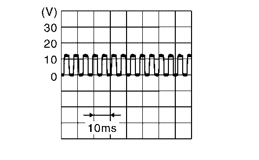
When stopped 0 V or 12 V 10 Moving (auto) When stopped 0 V or 12 V RH B162 7 Moving (auto) When stopped 0 V or 12 V 10 Moving (auto) When stopped 0 V or 12 V
Is the inspection result normal?
YES>>GO TO 10.
NO>>GO TO 9.
CHECK ENCODER OUTPUT SIGNAL CIRCUIT
Disconnect automatic back door control module and spindle unit connector.
Check continuity between automatic back door control module harness connector and spindle unit harness connector.
Spindle unit Automatic back door control module Continuity Connector Terminal Connector Terminal LH B70 7 B55 6 Yes 10 7 RH B162 7 8 10 9 Check continuity between automatic back door control module harness connector and ground.
Automatic back door control module Ground Continuity Connector Terminal B55 6 No 7 8 9
Is the inspection result normal?
YES>>Replace automatic back door control module. Refer to Removal and Installation.
NO>>Repair or replace harness.
REPLACE SPINDLE UNIT AND ERASE DTC
CONSULT
Ignition switch OFF.
Replace spindle unit.
Ignition switch ON.
Select “Self Diagnostic Result” mode of “AUTO BACK DOOR”.
Erase DTC, and then repeat “DTC CONFIRMATION PROCEDURE”. Refer to DTC Confirmation Procedure.
Is DTC “B2422-78” detected?
YES>>Replace automatic back door control module. Refer to Removal and Installation.
NO>>Inspection End.
CHECK INSTALLATION OF SPINDLE UNIT
Check that spindle unit is installed normally. Refer to Removal and Installation.
Is the inspection result normal?
YES>>GO TO 13.
NO>>GO TO 12.
ADJUST SPINDLE UNIT INSTALLATION AND ERASE DTC
CONSULT
Ignition switch OFF.
Adjust the spindle unit installation.
Ignition switch ON.
Select “Self Diagnostic Result” mode of “AUTO BACK DOOR”.
Erase DTC, and then repeat “DTC CONFIRMATION PROCEDURE”. Refer to DTC Confirmation Procedure.
Is DTC “B2422-78” detected?
YES>>GO TO 13.
NO>>Inspection End.
REPLACE SPINDLE UNIT AND ERASE DTC
CONSULT
Ignition switch OFF.
Replace spindle unit.
Ignition switch ON.
Select “Self Diagnostic Result” mode of “AUTO BACK DOOR”.
Erase DTC, and then repeat “DTC CONFIRMATION PROCEDURE”. Refer to DTC Confirmation Procedure.
Is DTC “B2422-78” detected?
YES>>Replace automatic back door control module. Refer to Removal and Installation.
NO>>Inspection End.
ERASE DTC
CONSULT
Fully close then back door manually.
Ignition switch ON.
Select “Self Diagnostic Result” mode of “AUTO BACK DOOR”.
Erase DTC, and then repeat “PERFORM DTC CONFIRMATION PROCEDURE”. Refer to DTC Confirmation Procedure.
Is DTC “B2422-79” detected?
YES>>GO TO 2.
NO>>Inspection End.
CHECK AUTOMATIC BACK DOOR CONTROL MODULE EACH DTC
If DTC “B2422-79” is displayed with DTC “B2426-23, B2426-24, B2426-29, B2427-23, B2427-24, B2427-29”, first perform the trouble diagnosis for DTC “B2426-23, B2426-24, B2426-29, B2427-23, B2427-24, B2427-29”.
Is DTC “B2426-23, B2426-24, B2426-29, B2427-23, B2427-24, B2427-29” detected?
YES>>Refer to DTC Index.
NO>>Replace automatic back door control module. Refer to Removal and Installation.