High-pressure pump
K9K
Essential special tools |
|
| Mot.1566 | High-pressure pump pipe removal tool |
| Mot. 1367-02 | Engine support |
| Mot. 1367 | Engine support bar for cylinder head replacement |
| Mot.1606 | High-pressure pump pulley holding tool |
| Mot.1525 | High-pressure pump pulley puller |
| Mot.1525-02 | High-pressure pump pulley puller jaws |
Essential equipment |
| diagnostic tool |
| "low torque" torque wrench |
| high-pressure pipe spanner (DM19 spanner) |
| crowfoot pipe attachment for tightening the injector-to-rail high-pressure pipes ("Crowfoot 18-17" spanner) |
| crowfoot pipe attachment for tightening the pump-to-rail high-pressure pipe ("Crowfoot 19-17" |
Tightening torques |
|
| high-pressure pump mounting bolts | 2.1 +/- 0.2 daN.m |
| rail mounting nuts | 2.8 +/- 0.3 daN.m |
| nut on rail side | 3.8 daN.m |
| nut on pump side | 3.8 daN.m |
| cover nut on rail | 2.1 daN.m |
| high-pressure injection pump mounting bolts | 2.1 +/- 0.2 daN.m |
| high-pressure injection pump pulley nut | 1.5 +/- 0.1 daN.m + 60 +/- 10 |
| rail mounting nuts | 2.8 +/- 0.3 daN.m |
| fitting on rail side | 3.8 daN.m |
| fitting on pump side | 3.8 daN.m |

There are two removal and refitting methods for the high-pressure pump.
IMPORTANTBefore any work on the injection system, use the diagnostic tool to check:
- that the injection rail is no longer under pressure,
- that the fuel temperature is not high.
- Always observe the safety and cleanliness instructions given in this document during every operation.
- Never loosen a high-pressure pipe connection while the engine is running.
- Use the special plug kit for the high-pressure injection circuit.
- Always replace any high-pressure pipe and high-pressure pipe clips that have been removed.
CAUTION: Never turn the engine in the reverse direction to its operating direction.
REMOVAL: METHOD 1
METHOD FOR HIGH-PRESSURE PUMPS WHOSE PULLEY IS MARKED NUMBER 070 575
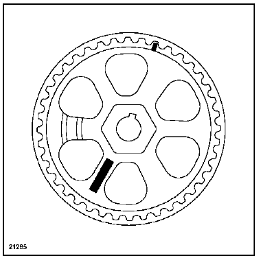
- It is strictly forbidden to remove any high-pressure pump pulley marked number 070575.
- Replace the "pump - pulley" assembly.
- Remove:
- the auxiliary drive belt (Chapter Upper and front engine, Auxiliary drive belt, page 11A-1),
- the timing belt (Chapter Upper and Front Engine, Timing Belt, page 11A-5).
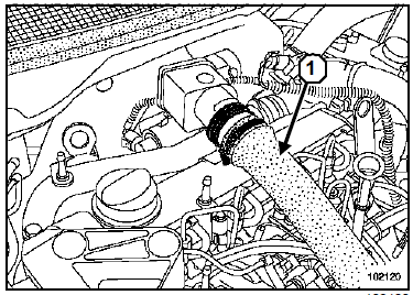
- Remove the engine covers.
- Disconnect:
- the battery,
- the air intake duct (1).
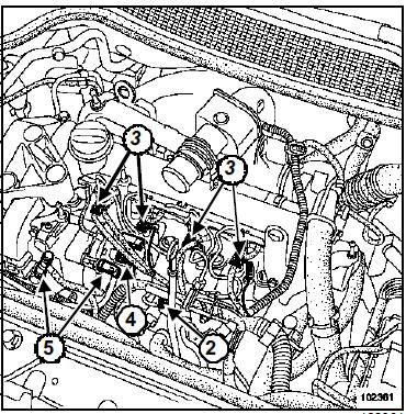
- Remove the oil dipstick guide tube (2) and plug the opening on the engine block.
- Carefully disconnect:
- the glow plugs (3),
- the injectors (3),
- the electrical connectors on the high-pressure pump (4),
- the supply and return pipes (5).
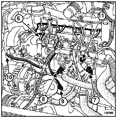
- Carefully disconnect:
- the return pipe (6) connecting the injectors to the pump,
- the rail pressure sensor (7),
- the accelerator pedal sensor (8),
- the oil level sensor (9),
- the cylinder identification sensor (10) on the timing cover.
- Plug all openings in the injection circuit.
- Release the wiring harness from its clips, then move it aside.
- Remove the cover (11) located on the fuel rail.
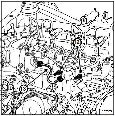
- Loosen the rail mounting nuts (12) by a few threads.
- Remove the high-pressure pipe (13) connecting the pump to the rail. To do this:
- loosen the pump-side nut, then the rail-side nut,
- slide the long pipe nut back while keeping the olive in contact with the cone.
- Plug all openings in the injection circuit.
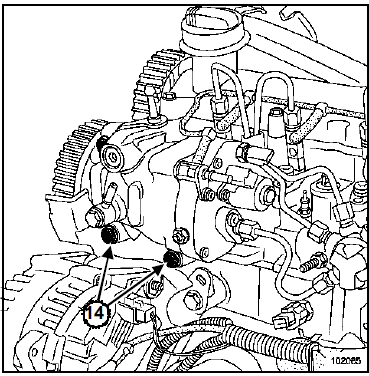
- Remove:
- the three high-pressure pump mounting bolts (14),
- the high-pressure pump.
REFITTING: METHOD 1
WARNINGRemove the protective plugs only at the last moment, for each component.
- Fit the high-pressure pump.
- Tighten the high-pressure pump mounting bolts to torque (2.1 +/- 0.2 daN.m).
CAUTION Always replace all high-pressure pipes that have been removed.
- Lightly lubricate the nut threads with the oil contained in the sachet supplied in the new parts kit, before fitting the new high-pressure pipe.
- Some pipes are supplied with a sachet of oil and some are supplied without one.
- Pipes supplied without a sachet are self-lubricated. The tightening torque is unchanged: 3.8 daN.m.
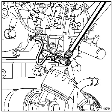
- To refit the high-pressure pipe:
- remove the protective plugs,
- insert the high-pressure pipe olive into the cone at the high-pressure pump outlet,
- insert the high-pressure pipe olive into the cone at the rail inlet.
- Hand-tighten the high-pressure pipe nuts, starting with the nut on the rail side.
- Pre-tighten slightly.
- Tighten the rail mounting nuts to torque (2.8 +/- 0.3 daN.m).
CAUTION Do not turn the pipes with the wrench when tightening to torque.
- Tighten in sequence and to torque:
- the nut on the rail side (3.8 daN.m),
- the nut on the pump side (3.8 daN.m),
using tool (Mot.1566) and if necessary:
- a "low torque" torque wrench,
- a high-pressure pipe spanner (DM19 spanner),
- a flare-nut crowfoot for tightening the injector-to-rail high-pressure pipes ("Crowfoot 18-17" spanner),
- a flare-nut crowfoot for tightening the pump-to-rail high-pressure pipe ("Crowfoot 19-17" spanner).
- Tighten the union nut on the rail to torque (2.1 daN.m) using the "low torque" torque wrench.
Connect the battery; carry out the necessary re-learns (see Electrical Equipment chapter).
WARNINGCheck for diesel leaks:
- check the seal after the repair (Diesel Injection chapter, High-pressure pipe: Sealing check, page 13B-48),
- run the engine at idle until the radiator fan starts,
- rev the engine several times with no load,
- carry out a road test,
- switch off the ignition,
- check that no diesel is leaking.
REMOVAL: METHOD 2
METHOD FOR HIGH-PRESSURE PUMPS WHOSE PULLEY BEARS A NUMBER OTHER THAN 070575
- Position the vehicle on a two-post lift.
- Remove the engine covers.
- Disconnect the battery.
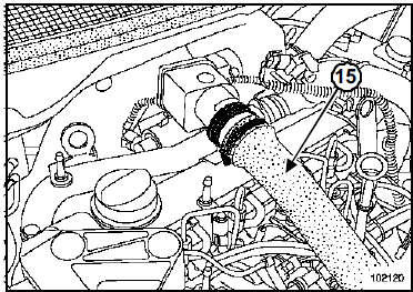
- Disconnect the air intake duct (15).
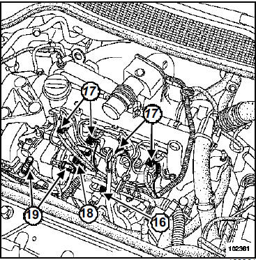
- Remove the oil dipstick guide tube (16) and plug the opening in the engine block.
- Carefully disconnect:
- the glow plugs (17),
- the injectors (17),
- the electrical connectors on the high-pressure pump (18),
- the supply and return pipes (19).
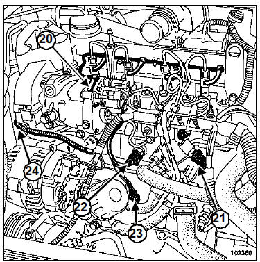
- Carefully disconnect:
- the return pipe (20) connecting the injectors to the pump,
- the rail pressure sensor (21),
- the accelerometer (22),
- the oil level sensor (23),
- the cylinder identification sensor (24) on the timing case.
- Release the wiring harness from its clips, then move it aside.
- Remove the cover (11) located on the fuel rail.
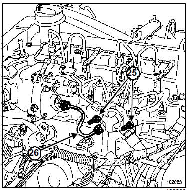
- Unscrew the rail mounting nuts (25) by a few threads.
- Remove the high-pressure pipe (26) between pump and rail (Diesel Injection chapter, High-pressure pipe: Replacement, page 13B-80).
- Loosen the nut on the pump side, then the nut on the rail side.
- Slide the nut along the pipe while keeping the olive in contact with the cone.
- Plug all openings in the injection circuit.
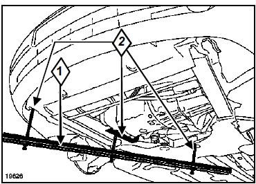
- Fit tool (Mot. 1367-02)(1) and tool (Mot. 1367).
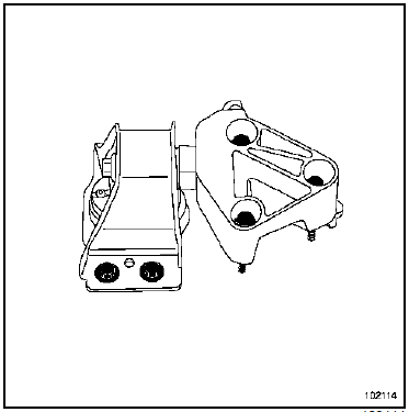
- Remove the right-hand engine mount bracket together with its cover.
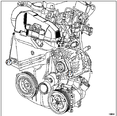
- Remove the upper timing cover by releasing the two tabs (27).
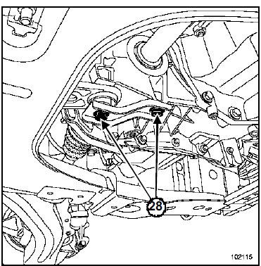
- Remove the mounting bolts (28) of the torque rod from the gearbox and from the engine cradle.
- Raise the engine a few centimetres to access the engine mount bracket mountings on the cylinder head and the high-pressure pump pulley.
CAUTION Do not disengage the right-hand driveshaft when raising the engine.
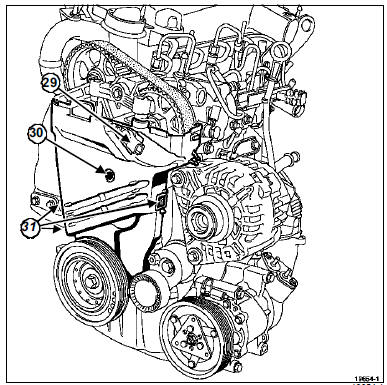
- Remove:
- the cylinder identification sensor (29),
- the plastic bolt (30).
- Release the three tabs (31).
- Remove the lower timing cover.
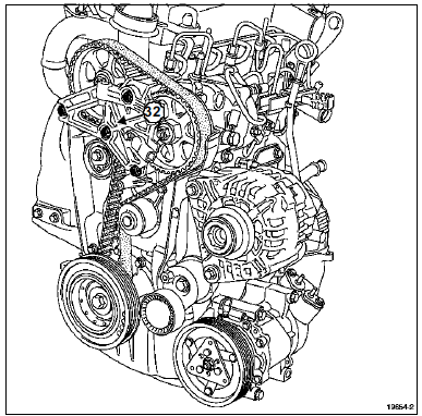
- Remove the engine mount bracket (32) from the cylinder head.
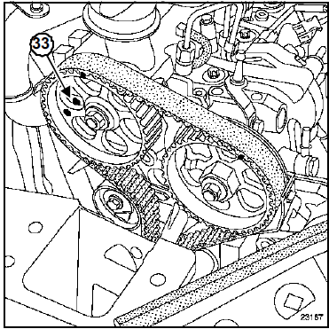
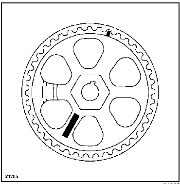
- Position the engine at top dead centre. The hole in the camshaft pulley must be aligned with the hole (33) in the cylinder head.
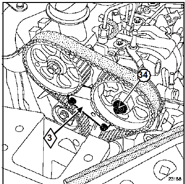
- Fit tool (Mot.1606)(3).
If necessary, turn the engine slightly to align the locking tool with the teeth of the pump pulley.
- Remove the high-pressure pump pulley nut (34) while holding the pulley with an open-ended spanner.
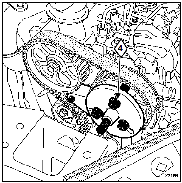
- Fit tool (Mot.1525)(4) with tool (Mot.1525-02).
Check that the tool thrust rod is aligned and bearing on the high-pressure pump shaft.
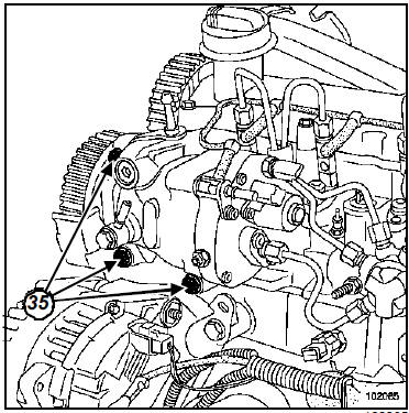
- Remove the three high-pressure pump mounting bolts (35).
- Screw in the thrust rod of tool (Mot.1525).
- Separate the pulley-pump assembly.
- Remove:
- the high-pressure pump,
- the high-pressure pump extractor tool.
REFITTING: METHOD 2
WARNINGRemove the protective plugs only at the last moment, for each component.
- Make sure the pulley locating pin is still in place.
- Fit the high-pressure injection pump.
- Tighten the high-pressure injection pump mounting bolts to torque (2.1 +/- 0.2 daN.m).
- Fit the nut for the high-pressure injection pump pulley.
- Tighten the high-pressure injection pump pulley nut to torque and angle (1.5 +/- 0.1 daN.m + 60 +/- 10°), holding the pulley with an open-ended spanner.
- Remove tool (Mot.1606).
CAUTION Always replace all high-pressure pipes that have been removed.
- Lightly lubricate the union threads with the oil contained in the sachet supplied in the new parts kit, before fitting the new high-pressure pipe.
- Some pipes are supplied with a sachet of oil and some are supplied without one.
- Pipes supplied without a sachet are self-lubricated. The tightening torque is unchanged: 3.8 daN.m.
- To refit the high-pressure pipe:
- remove the protective plugs,
- position the high-pressure pipe olive in the cone at the pump outlet,
- position the high-pressure pipe olive in the cone at the rail inlet.
- Hand-tighten the high-pressure pipe unions, starting with the union on the rail side.
- Tighten the rail mounting nuts to torque (2.8 +/- 0.3 daN.m).
- Tighten in sequence and to torque:
- the fitting on the rail side (3.8 daN.m),
- the fitting on the pump side (3.8 daN.m).
- Check the high-pressure circuit for leaks after repair (Diesel Injection chapter, High-pressure pipe: Leak test, page 13B-48).
- Refit in the reverse order of removal.
Prime the diesel supply circuit with the priming pump (bleeding is automatic).
Connect the battery; carry out the necessary re-learns (see Electrical Equipment chapter).
WARNINGCheck for diesel leaks:
- check the seal after the repair (Diesel Injection chapter, High-pressure pipe: Sealing check, page 13B-48),
- run the engine at idle until the radiator fan starts,
- rev the engine several times with no load,
- carry out a road test,
- switch off the ignition,
- check that no diesel is leaking.
F9Q
Essential special tools |
|
| Tool 1668 | High-pressure pump gear locking tool |
| Mot.1525 | High-pressure pump pulley puller |
| Tool 1525-03 | Adapter jaws for Tool 1525 (for 33-tooth pulley) |
Essential equipment |
| diagnostic tool |
| pipe union tool for tightening the high-pressure pump-to-rail pipe ("Crowfoot 19-17" spanner) |
| high-pressure pipe spanner (DM19 spanner) |
| "low torque" torque wrench |
Tightening torques |
|
| high-pressure pump mounting bolts on the pump brackets | 3 daN.m |
| high-pressure pump pulley nut | 7 daN.m |
| high-pressure pump bracket mounting bolts on the cylinder head | 2 daN.m + 80 |
| rear high-pressure pump bracket mounting bolt on the cylinder block | 4.4 daN.m |
| injection rail mounting nuts | 2.2 daN.m |
| high-pressure pump-to-rail pipe nuts | 2.5 daN.m |
| cover nut on rail | 2.1 daN.m |

Before any work on the injection system, use the diagnostic tool to check:
- that the injection rail is no longer under pressure,
- that the fuel temperature is not high.
Always observe the safety and cleanliness instructions given in this document during every operation.
Never loosen a high-pressure pipe connection while the engine is running.
WARNING- Use the special plug kit for the high-pressure injection circuit.
- Always replace any high-pressure pipe and high-pressure pipe clips that have been removed.
REMOVAL
- Position the vehicle on a two-post lift.
- Disconnect the battery.
- Remove:
- the auxiliary drive belt (Chapter Upper and front engine, Auxiliary drive belt, page 11A-1),
- the timing belt (Chapter Upper and Front Engine, Timing Belt, page 11A-5).
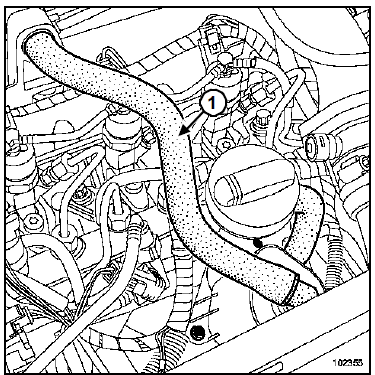
- Disconnect and move aside the oil vapour return pipe (1).
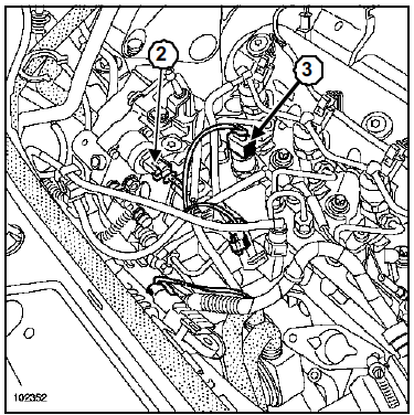
- Disconnect:
- the diesel heater on the diesel filter,
- the glow plugs,
- the pressure regulator (2),
- the pressure sensor (3).
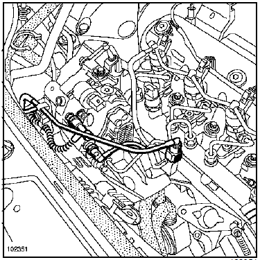
- Disconnect the diesel supply and return pipes.
- Fit protective caps to the openings.
- Remove the clip securing the diesel pipes.
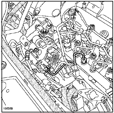
- Remove the high-pressure pump-to-rail pipe.
- Fit protective caps to the openings.
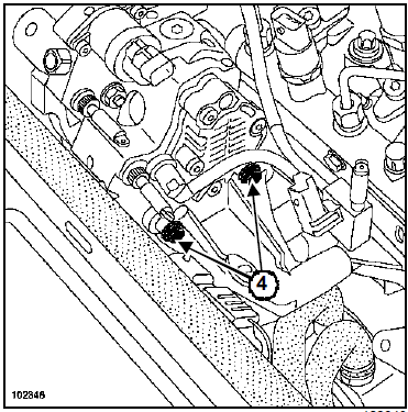
- Remove the two mounting bolts (4) of the high-pressure pump on the rear high-pressure pump bracket.
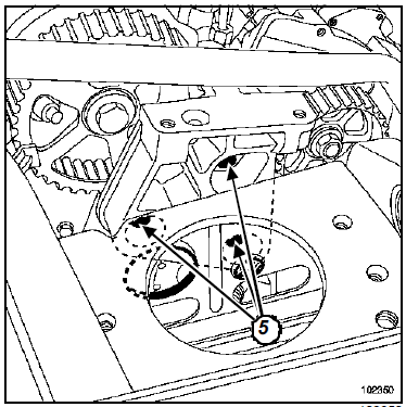
- Remove:
- the three mounting bolts (5) of the front high-pressure pump bracket,
- the high-pressure pump with the high-pressure pump bracket.
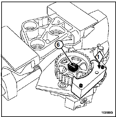
- Fit the tool (Tool 1668)(1).
- Remove the nut (6) from the high-pressure pump pulley.
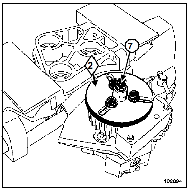
- Fit the pulley puller (Tool 1525)(2), fitted with the jaws (Tool 1525-03) for the 33-tooth pulleys.
- Pull off the pulley by tightening the puller pressure screw (7).
- Remove the tools (Tool 1525), (Tool 1525-03), (Tool 1668).
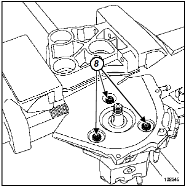
- Remove:
- the three mounting bolts (8) of the high-pressure pump,
- the high-pressure pump.
INSTALLATION
WARNINGRemove the protective plugs only at the last moment, for each component.
- Refit the high-pressure pump on the pump bracket.
- Tighten to the following torques:
- the high-pressure pump mounting bolts on the pump brackets (3 daN.m),
- the high-pressure pump pulley nut (7 daN.m), holding the pulley still with the tool (Tool 1668).
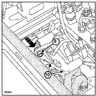
- Push back the ring (9) as shown in the illustration.
- Loosen the two mounting bolts (10) of the rear high-pressure pump bracket on the cylinder block.
- Refit the complete high-pressure pump and pump bracket assembly.
- Tighten the high-pressure pump bracket mounting bolts on the cylinder head to torque (2 daN.m + 80 ).
Do not stress the high-pressure pump-to-rail pipe or the rear pump bracket.
I - REFITTING THE REAR HIGH-PRESSURE INJECTION PUMP BRACKET
- Start the mounting bolts by hand so that the bracket contacts the high-pressure pump and the cylinder block.
- Tighten the rear high-pressure pump bracket mounting bolts on the cylinder block to torque (4.4 daN.m).
II - REFITTING THE HIGH-PRESSURE PUMP-TO-RAIL PIPE
- Loosen the injection rail mounting bolts (the rail must be "floating").
- Before fitting a high-pressure pipe, lightly lubricate the nut threads with the oil in the sachet supplied in the new parts kit.
- Take care not to introduce oil into the high-pressure pipe.
- Do not lubricate high-pressure pipes supplied without a sachet; these pipes are self-lubricated.
CAUTION: Remove the caps only at the last moment for each component.
- Seat the high-pressure pipe flared end in the high-pressure outlet cone of the high-pressure pump.
- Seat the high-pressure pipe flared end in the inlet cone of the common rail.
- Start the high-pressure pipe nuts by hand, beginning with the rail-side nut.
- Pre-tighten the high-pressure pipe nuts lightly.
- Tighten the injection rail mounting nuts to torque (2.2 daN.m).
- Do not put the spanner on the high-pressure pipes when tightening to torque.
- Always hold the injector intermediate fitting with a spanner while tightening.
- Tighten the high-pressure pump-to-rail pipe nuts (2.5 daN.m) in sequence and to torque, on both the pump side and the rail side, using the pipe union tool ("Crowfoot 19-17" spanner) or the high-pressure pipe spanner (DM19 spanner),
Note: Fully tighten one pipe before moving to the next pipe.
- Refit in the reverse order of removal.
- Refit:
- the timing belt (Section Top and front of engine, Timing belt, page 11A-5),
- the drive belt (Chapter Upper and front engine, Drive belt, page 11A-1).
- Prime the diesel circuit using the priming bulb.
- Tighten the union nut on the rail to torque (2.1 daN.m) using the "low torque" torque wrench.
Connect the battery; carry out the necessary re-learns (see Electrical Equipment chapter).
WARNINGCheck for diesel leaks:
- Check for leaks after repair (Diesel Injection chapter, High-pressure pipe: Leak test, page 13B-48).
- Run the engine at idle until the cooling fan starts.
- Rev the engine several times without load.
- Carry out a road test.
- Switch off the ignition.
- Check that there is no diesel leakage.
Test yourself
A quick Renault Megane quiz: every answer comes with an explanation and a link to the manual page.