Engine Control System/Fuel System
WGT Actuator Repair Procedures
In this manual: Engine Control System/Fuel System
30steps
~180min
4/5difficulty
Done 0 of 30
Inspection
[Motor]- Turn the ignition off.
- Disconnect the EWGA connector.
- Make sure the EWGA is not caught by foreign material.
- Measure the resistance between the motor control terminals (+) and (-) of the motor.
- Make sure the resistance is within specification.
Specification: Refer to "Specifications"
- Turn the ignition off.
- Connect the GDS to the Data Link Connector (DLC).
- Check the output voltage at each EWGA position sensor position using the current data item. It should be within specification.
Specification: Refer to "Specifications"
Removal
- Turn the ignition switch OFF and disconnect the negative (-) battery cable.
- Raise the vehicle.
- Disconnect the EWGA connector (A).
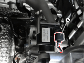
- Remove the exhaust manifold heat shield. (Refer to Engine Mechanical System - "Exhaust Manifold")
- Remove the link shaft assembly (B) after removing the C-clip (A).
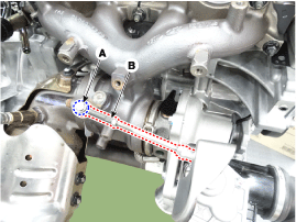
- Remove the turbocharger water pipe mounting bolt (A).
- Remove the EWGA after removing the bolts (B).

When carrying the turbocharger, do not hold the turbocharger shaft, to avoid bending the shaft.
Installation
- Install in the reverse order of removal. WGT actuator installation torque: 11.8 ~ 13.7 N·m
Adjustment
- Make sure the turbocharger wastegate valve has cooled sufficiently before working on it.
- Turn the ignition switch to the OFF position.
- Connect the diagnostic tester to the DLC (16-pin) located under the instrument panel on the driver's side.
- Turn the ignition switch to the ON position.
Do not start the engine. - Select VIN or Vehicle on the initial screen.
- After selecting the vehicle information (model, model year, engine type) or entering the VIN, select the Engine Control menu.
- After selecting the Current Data menu, check the "EWGA Lower Mechanical Stopper Adaptation Value".
Specified voltage: 4.1 ~ 4.3 V
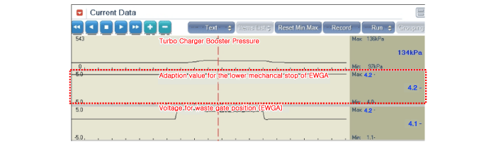
- If the measured voltage is not within the specified voltage, adjust the EWGA rod length. If it is not adjusted, the following procedure is mandatory.
- Loosen the rod end lock nut (A) and remove the C-clip (B).
- Adjust the rod end part (C) by turning it clockwise (D) or counterclockwise (E) as specified.
A. If the output voltage > 4.3 V: Turn clockwise (D). B. If the output voltage < 4.1 V: Turn counterclockwise (E). Steering Wheel Angle Change in adaptation value level (V) 0.5 turn (180°) 0,15 ~ 0,20 1 turn (360°) 0,30 ~ 0,40
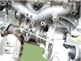
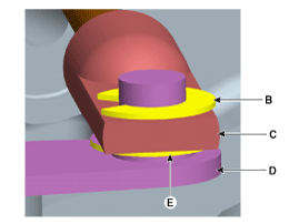
- Temporarily install the rod end (C) to the turbocharger lever (D). Do not tighten the rod end lock nut (A).
- Turn the ignition switch ON/OFF 5 times. Hold for 5 seconds in each IG ON or OFF state.
Turn the ignition switch ON and OFF several times until the "EWGA Lower Mechanical Stopper Adaptation Value" changes within 0.05 V. Maximum change of the adaptation value per ignition ON or OFF: Max. ±0.05 V
- If the measured voltage is not within the specified voltage, repeat steps 8 through 10 until the voltage is within the specified voltage.
Specified voltage: 4.1 ~ 4.3 V
- Make sure the "EWGA Lower Mechanical Stopper Adaptation Value" is within the specified voltage.
- If it is within the specified voltage, install the turbocharger lever (D) and the rod end (C).
Be careful not to remove the washer (E). - Tighten the rod end lock nut (A). The turbocharger lever side (D) and the rod end (C) side must be parallel at this time.
- Install the C-clip (B).
Test yourself
A quick Hyundai Sonata LF quiz: every answer comes with an explanation and a link to the manual page.
Was this page helpful?