Power Window System
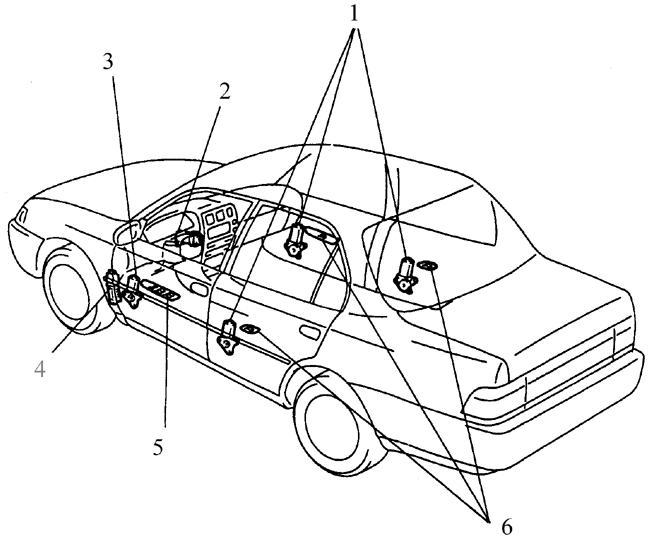
Component Location - Power Window System 1. Power Window Motors
2. Ignition Switch
3. Power Window Motor
4. Fuse Block No. 1 (Power Window Fuse)
5. Master Switch Assembly
6. Power Window Switches
The power window system is based on electric motors installed in the doors that raise and lower the windows. The power window system consists of switches, motors (regulators), windows and connecting wires.
The window regulators are connected so that the windows can be lowered or raised using the master switch assembly at the driver's position or using switches located directly on the doors. Each door has a separate motor that can run in both directions to raise and lower the window.
The switch position determines the polarity and thus the direction of motor operation. Some models have relays that control the electric current supplied to the power window motors.
Some models have a separate circuit breaker for each power window motor in addition to the fuse or circuit breaker protecting the entire circuit. This prevents one failed power window from disabling the entire system.
The power windows operate only when the ignition switch is in the ON position. Also, when activated, the lock-out switch on the master switch assembly can disable the switches on all doors, including the front passenger door. Always check the condition of this switch before starting system diagnosis.
Diagnostic procedures available to a do-it-yourself owner are fairly limited, so if you cannot locate the source of the fault yourself, consult a specialist.

Tester Connection and Continuity Table for the Power Window Master Switch Assembly
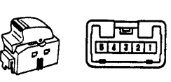
Tester Connection and Continuity Table for the Power Window Switch on the Vehicle Door
Inspection
PROCEDURE
1. If the power windows do not operate, check the fuse or circuit breaker.
2. If only the rear power windows do not operate, or if the power windows respond only to the master switch, check the rear window lockout switch for continuity in the OFF position (see table Tester Connection and Power Window Switch Continuity Chart for the door switch). Replace the switch if there is no continuity.
3. Check the wires between the switches and the fuse panel for continuity. Repair the connection if there is an open circuit.
4. If only one power window does not respond to the master switch, try to lower or raise this window using the door-mounted switch. The driver's door window is an exception.
5. If this power window responds to the door switch but does not respond to the master switch, check the switch for continuity (see table Tester Connection and Master Power Window Switch Continuity Chart).
6. If the switch is good, check the wires between this switch and the power window motor for a short circuit or open circuit.
7. If the power window does not respond to either switch, remove the door trim panel of the door where this power window is installed and check for voltage at the motor when the switch is operated.
8. If there is voltage at the motor, disconnect the window from the regulator. Raise or lower the window by hand and check whether it is bent or damaged. Also check whether the regulator is bent or damaged. If the regulator is not damaged and the window moves up and down freely, replace the motor. If the window or regulator is damaged or deformed, lubricate, replace, or repair the faulty parts.
9. If there is no voltage at the motor, check the wires between the switches and the motors for continuity. You will need to refer to the vehicle wiring diagrams. The circuits of some power windows are protected by relays. If present, check that they are securely grounded and that voltage is supplied to them from the switches. Also check that each relay supplies voltage to the motor when the switch is operated. If not, replace the relay.
10. Check the operation of the power windows after the work is completed.
Test yourself
A quick Toyota Corolla quiz: every answer comes with an explanation and a link to the manual page.