Central Locking System

Component Location - Power Door Lock System 1. Fuse Block No. 2 (AM1 Fuse)
2. Ignition Switch (Indicator Lamp Switch)
3. Door Lock Control Relay
4. Fuse Block No. 1 (Power Window Fuse)
(Instrument Panel Fuse)
5. Door Lock Switch
6. Door Locks (Lock Motor)
(Lock Position Switch, Checks Lock Closure)
The power door lock system operates the door lock actuators, which are located in each door.
The system consists of switches, actuators and connecting wires.
Diagnosis is usually limited to checking the wire connections and actuators for minor faults that are easy to repair.
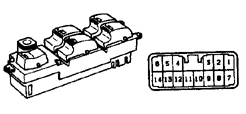
Tester Connection and Continuity Table for the Power Door Lock Master Switch
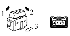
Tester Connection and Continuity Table for the Door Lock Switch 1. Locked
2. Unlocked
3. Front
Inspection
PROCEDURE
1. The power door lock system uses double-acting solenoids to lock and unlock the door locks. The lock switches have two operating positions: Lock and Unlock. These switches operate a relay, which in turn supplies voltage to the door lock solenoids. Depending on the signal sent to the relay, it changes polarity, allowing both sides of the circuit to have positive or negative voltage.
2. Always check the electrical circuit protection first. Some vehicles use circuit breakers and fuses together.
3. Move the switches to both positions (Lock and Unlock) with the engine off. Listen for the faint click of the relay operating.
4. If no click is heard, check for voltage at the switches. If voltage is present, check the wires between the fuse block and the switches for short circuits or open circuits.
5. If voltage is present but no click is heard, check the switch for continuity. Replace the switch if it does not conduct in either position (see Tester Connection and Continuity Table for the Power Door Lock Master Switch).
6. If the switch conducts but the relay does not click, check the wires between the switch and the relay. Repair the connection if there is an open circuit in the wiring.
7. If the relay receives power from the switch but does not send it to the solenoids, check the relay body ground. If the relay body ground is good, replace the relay.
8. If the solenoids of all locks work except one, remove the trim panel from that door (see subsection 11.12) and check for voltage at the solenoid while operating the lock switch. One wire should have voltage when the switch is in the Lock position; the second wire should have voltage when the switch is in the Unlock position.
9. If voltage is present at the non-working solenoid, replace it.
10. If there is no voltage at the non-working solenoid, check the wire between the solenoid and the relay for an open circuit.
* Wires often break in the part of the wiring harness located between the body and the door (constant opening and closing of the door causes wire fatigue and, eventually, wire breakage).
Test yourself
A quick Toyota Corolla quiz: every answer comes with an explanation and a link to the manual page.