Airbag System
The supplemental restraint system, more commonly known as the airbag system, may be fitted in various configurations, either as standard equipment or as optional equipment, depending on the vehicle model and sales market.
The airbag system is designed to protect the driver and the front seat passenger from serious injury in the event of a frontal collision.
The system consists of airbags installed in the center of the steering wheel and on the right side of the instrument panel, two impact sensors installed at the front of the vehicle (for models produced before 1995), and a central sensor located in the vehicle interior.
On some models, pyrotechnic seat belt pretensioners are installed in place of conventional seat belt retractors to tighten the belts in the event of a frontal collision.
Airbag Module
The airbag module consists of a housing with a front cover (the airbag) and an inflator unit mounted on the back of the housing above the opening through which gas enters the airbag, inflating it almost instantly when an electrical signal is received.
The special coiled wire that transmits the signal to the driver airbag module is called the clock spring.
The clock spring is a flat ribbon capable of conducting electrical current, which is coiled many times so that it can transmit the electrical signal regardless of the steering column position.
Sensors
On models produced before 1995, the airbag system has three sensors: two impact sensors at the front of the vehicle behind the bumper and slightly above the wheel wells, and a safing sensor located in the central airbag electronic control unit mounted in the center console. On 1996 model year vehicles, all sensors are installed in the central airbag electronic control unit.
The front impact sensors are pressure-activated switches that close the electrical circuit in the event of a collision of sufficient force. The electrical signal from the impact sensors is sent to the safing sensor located in the central airbag electronic control unit, which closes the circuit and inflates the airbag.
Central Airbag Electronic Control Unit
The central airbag electronic control unit includes the safing sensor and a microprocessor that monitors system operation. It checks the airbag system each time the engine is started, turns on the AIRBAG warning lamp on the instrument cluster, and turns it off if the system is operating normally. If a malfunction is detected in the airbag system, the lamp will illuminate and remain on, and the central electronic control unit will store the fault code. If the AIRBAG warning lamp illuminates and does not go out, the vehicle must be taken to a repair facility immediately for service.
Seat Belt Pretensioners
In addition to the airbags, the supplemental restraint system may also include pyrotechnic seat belt pretensioners, which are activated by gas cartridges located in the seat belt pretensioners. The pyrotechnic pretensioners are triggered by a signal sent from the central airbag electronic control unit, together with the airbags, to increase seat belt tension and provide additional protection in a collision.
WORK ON COMPONENTS LOCATED NEAR THE SUPPLEMENTAL RESTRAINT SYSTEM
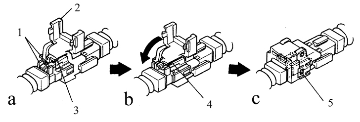
Supplemental restraint system components a). Primary lock not engaged
1. Ribs
2. Secondary lock
3. Primary lock
b). Primary lock engaged
4. Locked
c). Double lock engaged
5. Locked
Each airbag system connector uses a two-lock system to ensure a secure connection.
* Be careful when disconnecting airbag system connectors.
It may be necessary to remove the steering wheel, radio, or other components located near or on the instrument panel. In this case, you will be working in close proximity to the supplemental restraint system wires and connectors.
Supplemental restraint system wiring is easy to identify; it has bright yellow insulation.
Do not disconnect the supplemental restraint system wiring connectors unless it is necessary to disable the system. Also, do not use electronic test equipment on the system wiring.
Always disable the supplemental restraint system before beginning work near system components or wiring.
Disabling the Supplemental Restraint System
PROCEDURE
1. Turn the steering wheel to the center position, turn the ignition key to the Lock position, and remove the key.
2. Disconnect the negative battery cable. Wait a few minutes for the backup capacitor to discharge.
3. Disconnect the yellow connectors at the base of the steering column and on the right side under the instrument panel, as described below.
Driver Airbag
PROCEDURE
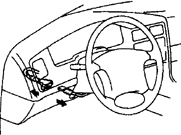
1. Remove the lower steering column trim panel under the instrument panel (refer to Subsection 11.23) to access the airbag system connector.
2. Disconnect the driver airbag wiring connector.
Passenger Airbag
PROCEDURE
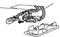
1. Open the glove box and remove the cover inside the glove box to access the airbag connector (see Subsection 11.20).
2. Disconnect the yellow connector of the front passenger airbag inflator.
Enabling the Supplemental Restraint System
PROCEDURE
1. After disabling the airbag and completing the necessary repair or service operations, connect the driver and passenger airbag connectors. Install the lower steering column trim panel and the glove box cover.
2. Connect the negative battery cable.
3. Turn the ignition key to the ON position and check that the AIRBAG warning light illuminates for approximately six seconds and then goes out.
Test yourself
A quick Toyota Corolla quiz: every answer comes with an explanation and a link to the manual page.