Steering Column Switches
* These models are equipped with an airbag, which may deploy (inflate) when connected to the battery. Disconnect the negative battery cable and wait at least two minutes before starting work on the airbag.
* If your vehicle's stereo has an anti-theft code system, make sure you know the radio activation code before disconnecting the battery.
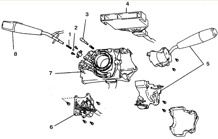
Components of the Steering Column Combination Switch
1. Spring
2. Ball
3. Horn Contact
4. Connector
5. Wiper Switch
6. High/Low Beam Headlight Switch
7. Base
8. Headlight Switch
Removal
PROCEDURE
1. Disconnect the negative battery cable.
2. Remove the steering column cover (see sub-section 11.22) and the lower instrument panel trim (sub-section 11.23).
3. Follow the wire harness of the switch to be inspected to the connector.
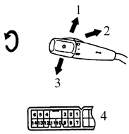
Headlight Switch Tester Connection and Continuity Chart1. Right-side turn signals
2. Hazard warning
3. Left-side turn signals
4. Combination switch connector
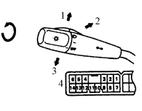
Turn Signal Switch Tester Connection and Continuity Chart
1. Right-side turn signals
2. Hazard warning
3. Left-side turn signals
4. Combination switch connector
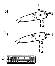
Windshield Washer and Wiper Switch Tester Connection and Continuity Chart
a). Wiper switch with fog driving function
1. Fog driving wiper operation
2. On
3. Low
4. High
b). Wiper switch with intermittent function
1. On
2. Intermittent
3. Low
4. High
c). Combination switch connector B
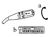
Rear Window Washer and Wiper Switch Tester Connection and Continuity Charta. Washer
b. Combination switch connector B
Inspection
PROCEDURE
1. Disconnect the switch connector and, using an ohmmeter, check the continuity between the specified terminals when the switches are in each of the specified positions.
2. If there is no continuity, replace the faulty switch.
Replacement
PROCEDURE
1. Remove the combination switch (see sub-section 12.6). Remove the four screws securing the airbag clock spring and detach the clock spring from the combination switch.
2. Remove the mounting screws of the switch to be replaced and remove the faulty switch.
3. Pull the wires of the switch being replaced out of the main wire harness and disconnect them from the connector.
4. Pull the wires of the switch being replaced out of the main wire harness and disconnect them from the connector.
5. Press the tabs at the rear of the connector and remove the cover. At the front of the connector, insert a small screwdriver or pin and depress the lock retaining the terminal, then remove the terminal from the rear of the connector.
6. Insert the terminals of the new switch into the connector until the locks securely retain the terminals.
7. Installation is performed in the reverse order of removal. Following the instructions (see sub-section 10.16), adjust the clock spring before installing the steering wheel.
Test yourself
A quick Toyota Corolla quiz: every answer comes with an explanation and a link to the manual page.