Timing belt work
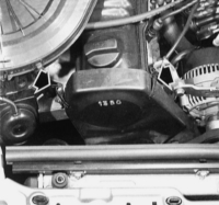
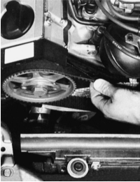
On the 4-cylinder engine, the timing belt cover is removed after loosening both retaining clips.
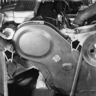
Remove the timing belt cover of the 5-cylinder engine after loosening both retaining clips (arrows).
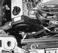
On the 6-cylinder engine, the timing belt cover is also secured with retaining clips (arrows). To remove the right half of the cover, additionally remove the poly-V belt tensioner roller (large bolt with internal hex).

The timing belt (2) of the 4-cylinder engine is correctly tensioned if it can be twisted 90° between the camshaft timing belt sprocket (1) and the intermediate shaft sprocket (position (3) indicates the position).
Check the timing belt tension on the 5-cylinder engine (illustration left) and the 6-cylinder engine (illustration right) in the same way as already described in the caption for the 4-cylinder engine illustration. The timing belts must be tensioned so that they can be twisted 90°. The illustrations show the check points.
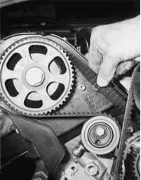
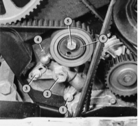
Shown here is the thermostatic tensioner roller of the 5-cylinder engine.
1 and 3 – mounting bolts;
2 – hex, into which the wrench is inserted when tensioning the timing belt;
4 – thermo-element;
5 – mounting bolt for tensioner roller (6).
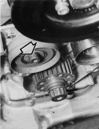
Left: timing belt tensioner roller of the 4-cylinder engine:
1 – clamping bolt;
2 – the timing belt tensioning tool can be placed here. The arrow shows the direction to turn to tension the belt.
Right: the tensioner roller (arrow) of the 6-cylinder engine is located at the front right on the cylinder block.

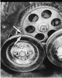
Left: on the 4-cylinder engine, when installing the timing belt, the mark on the intermediate shaft gear and the mark on the V-belt pulley (indicated by arrows) must be aligned.
Right: the marks on the camshaft timing belt sprocket (2) must align with the arrow mark (1) on the rear of the timing belt cover.
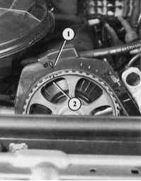
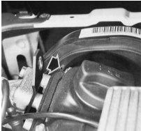
On the 5-cylinder engine, the camshaft TDC mark for cylinder 1 is located on the back side of the timing belt sprocket. The rear of the timing belt cover has a slot (arrow) through which you can check that the mark is exactly at the upper edge of the cylinder head cover.
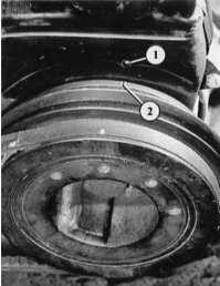
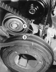
On the 5-cylinder engine, TDC marks are also located on the crankshaft pulleys. Positions (1) and (2) show the marks with the timing belt cover installed; positions (3) and (4) show the TDC position with the timing belt cover removed.
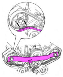
Left: the illustration shows how to install special tool 3243 on the 6-cylinder engine to lock the camshafts at TDC.
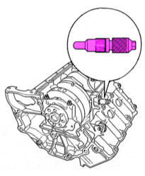
Right: the illustration shows tool 3242 and the point in the crankcase where it must be screwed in to lock the crankshaft.
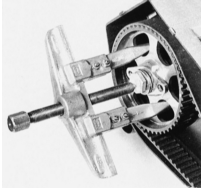
Removing the camshaft timing belt sprocket with the locking bolt loosened, using a puller with claws.
The valves are driven, as already mentioned, by the camshaft timing belt. It turns the camshaft at half the crankshaft speed. The timing belt also drives: the coolant pump (models with 5- and 6-cylinder engines) and the intermediate shaft (models with 4-cylinder engines).
Test yourself
A quick Audi 80 quiz: every answer comes with an explanation and a link to the manual page.