Removal and Installation of Cylinder Head
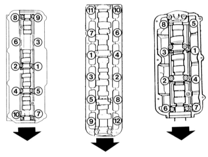
The cylinder head bolts must be tightened in the sequence shown by the numbers. Illustrated (left to right) are the 4-, 5- and 6-cylinder engines. Arrows indicate the direction of movement.
A torque wrench is required for this work. You will also need a long multi-spline socket T 55 (for 4- and 5-cylinder engines) or an external Torx socket E 14 (6-cylinder engine), and a new gasket for installing the cylinder head.
Removal on 4- and 5-cylinder engines
PROCEDURE
Disconnect the negative battery cable.
Engine with Mono-Motronic injection: remove the air filter.
Drain and collect the coolant.
Loosen the cooling system hoses on the cylinder head.
Remove the ignition distributor cap together with the high-voltage wires (5-cylinder engine) (refer to the Ignition System chapter).
Disconnect the throttle cable.
5-cylinder engine: remove the power steering pump and place it in the engine compartment; the hoses remain connected. Do not kink the lines.
Mark and disconnect all electrical wires near the cylinder head and the injection unit or intake manifold.
Disconnect the fuel supply lines of the injection system at the connecting fittings.
Mark and remove the vacuum hoses on the intake manifold or throttle body, as well as the vacuum hoses from the brake booster.
On the 5-cylinder engine, remove the upper part of the exhaust manifold (refer to the KE-III-Jetronic Injection System section). Also remove the injectors, leaving the high-pressure fuel lines connected.
Pack the injectors in clean, fuel-resistant plastic bags.
Disconnect the connectors from the cold start valve and set them aside with the fuel line connected.
Mark and disconnect the injection system connectors. Helpful for installation: the connectors have different colors.
5-cylinder engine: remove the air-fuel mixture corrector together with the air filter housing.
Disconnect the exhaust pipe from the exhaust manifold.
On the 4-cylinder engine, remove the upper generator mounting bolt. Loosen the V-belt first.
Remove the timing belt cover, loosen the timing belt and remove it from the camshaft gear.
Remove the cylinder head cover.
Loosen the cylinder head bolts in the reverse order of the sequence shown in the illustration at the top right. The engine must be cold first, because a hot cylinder head may warp after removal.
Remove the cylinder head together with the intake and exhaust manifolds, and the ignition distributor (5-cylinder engine). If it does not come off easily, carefully tap it with a plastic hammer.
This description applies to the left cylinder head. Removal of the right cylinder head is performed in the same way.
Removal on 6-cylinder engine
PROCEDURE
Remove the engine guard and the V-belt cover.
Remove the V-belt (refer to the Generator section).
Remove the timing belt (refer to the procedure earlier in this chapter).
Disconnect the exhaust pipe from the exhaust manifold.
Drain the coolant through the threaded drain plugs on the engine and the radiator, at the bottom right.
Disconnect the air duct from the exhaust manifold.
Disconnect the Hall sensor connector.
Disconnect the crankcase ventilation hoses on the left cylinder head and on the right cylinder head.
Disconnect the intake hose from the air filter.
Disconnect the air conditioning and/or differential lock vacuum hose from the left side of the throttle body housing.
Press the air duct down and remove it together with the crankcase ventilation hoses.
Detach the accelerator cable protective bracket, hang up and release the accelerator cable.
Disconnect the electrical connector of the intake air temperature sensor and the idle speed control valve.
Disconnect the fuel supply and return lines.
Disconnect the ground connection behind the throttle body.
Disconnect the vacuum line leading to the control unit in front of the throttle body.
Disconnect the electrical connector on the throttle body.
Unscrew the vacuum line to the charcoal canister valve on the right side of the throttle body.
Disconnect the spark plug wire terminals from all spark plugs.
Disconnect all electrical connectors from the fuel injectors.
Disconnect the knock sensor and oxygen sensor heater connectors.
Disconnect the oxygen sensor connectors and release the wiring.
Disconnect the electrical connector to the hydraulic oil pressure switch and the oil temperature sensor (rear, left cylinder head).
Remove the connector from the electronic thermal switch in the radiator water pipe.
Disconnect the vacuum line (blue) from the check valve in the line to the brake booster.
Remove the connectors from the fuel injectors on the left and right.
Unscrew the pipe brackets on the exhaust manifold. Do not separate the pipe.
Unscrew and remove the exhaust manifold.
Cover the openings with clean lint-free cloth.
Unscrew the coolant pipe at the rear of the cylinder head.
Remove the carbon monoxide intake tube.
Remove the oxygen sensor.
Disconnect the sheet metal heat shield of the exhaust manifold.
Remove the cylinder head cover.
Remove the rear section of the timing belt cover.
Disconnect the hoses from the coolant reservoir to the pump on the cylinder head.
Loosen the cylinder head bolts in the reverse order to that shown in the illustration at the top right. The engine must be cold beforehand, as a warm cylinder head may distort after removal.
Remove the cylinder head together with the intake and exhaust manifolds and the distributor (5-cylinder engine). If it does not come off without force, assist by lightly tapping with a plastic hammer.
Installation
All engine types
PROCEDURE
If installing a new cylinder head, lightly lubricate the hydraulic tappet guide bores with oil. Lubricate and install the camshaft as described previously.
If necessary, install the threaded plug in the replacement cylinder head of the 6-cylinder engine.
The threads on the cylinder head bolts and in the corresponding holes in the cylinder block must be clean and undamaged; otherwise the tightening torque will not be correct when tightening the bolts.
There must be no oil or water in the cylinder block bolt holes, otherwise the cast iron in the thread area may crack.
Turn the crankshaft slightly backward, against the direction of rotation, so that no piston is at TDC. Otherwise an open valve may collide with a piston when the cylinder head is installed.
Place the cylinder head gasket on the cylinder block so that the part number or the marking "oben" ("top") faces the cylinder head.
Install the cylinder head. In the workshop, two guide bolts are used for 4- and 5-cylinder engines. Without these aids, the gasket and the cylinder head will constantly shift.
You can make this tool yourself from two old cylinder head bolts: saw off the bolt head and cut a slot at the top (for turning with a screwdriver).
After installing several cylinder head bolts, the guide bolts can be removed.
Screw in all cylinder head bolts and tighten them in the sequence above to the following torque:
| Engine | 4-, 5-cylinder | 6-cylinder |
| First stage tightening | 40 N·m | (none) |
| Second stage tightening | 60 N·m | 60 N·m |
| Third stage tightening | Turn the bolts with a torque wrench by a half turn without removing the wrench (in the same sequence). Alternatively, turn them twice by a quarter turn | |
The bolts are now fully tightened and must under no circumstances be tightened again.
When assembling, observe the adjustment of the accelerator cable and the installation of the fuel injectors on the 5-cylinder engine (see Fuel Injection chapter).
Important: observe the tightening sequence when installing the exhaust manifold on the 6-cylinder engine.
In addition, check the ignition timing on 4- and 5-cylinder engines (see Ignition System chapter).
Test yourself
A quick Audi 80 quiz: every answer comes with an explanation and a link to the manual page.