Wiring diagrams
A passenger car has up to 1000 meters of wiring to supply all electrical consumers (headlights, radio, etc.) with power.
To trace a fault in the electrical system or to retrofit electrical accessories, a circuit diagram is essential, as it shows the current path and thus the cable connections. To keep the wiring clear, the circuit diagram shows only individual circuits in detail diagrams. In principle, the circuit concerned must be closed, otherwise electric current cannot flow. For example, it is not sufficient for voltage to be present at the positive terminal of a headlight if the circuit is not simultaneously closed via the ground connection.
The battery ground cable is therefore also connected to the body. Sometimes this ground connection is not sufficient, and the consumer in question receives a direct ground wire. Individual circuits may include switches, relays, fuses, measuring instruments, electric motors or other electrical components.
The most practical way to use the wiring diagram is as follows: first find the component in the legend, for example the switch for the heater blower. The corresponding number is shown next to the component name. This number appears again in the wiring diagram next to the corresponding component.
To read the wiring diagram, you need to know some components. You should also know the most important circuit symbols.
All switches and consumers are shown in the at-rest position.
The changed current flow after a switch is operated is explained using the example of a two-stage switch:
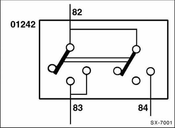
When the first stage of the switch is pressed, current flows from terminal 82 through terminal 83. The bridge of the second switch stage moves to the center position, but without making a connection. Only when the second switch stage is pressed does the bridge of the second stage move from internal line 82 to 84 and pass current on through 84. The current flow of the first switch stage remains through the internal connection in the switch, the line angled to the right from 83.
Relays and switches often have several connections. To connect these components correctly, the individual contacts have corresponding terminal designations.
The most important terminal designations are: terminal 30. Battery voltage is always present at this terminal. The cables are usually red.
Terminal 31 is the ground connection. Ground wires are usually black.
Terminal 15 is supplied through the ignition switch. These wires carry current only when the ignition is switched on.
In the wiring diagram, the colors of the individual wires are marked with letters or letter combinations.
The fuse and relay box with the fuses and relays is shown with the corresponding fuses in every detailed diagram.
For fuse and relay allocation, see page 248.
Test yourself
A quick Fiat Bravo quiz: every answer comes with an explanation and a link to the manual page.