Brake system
The brake system consists of the master cylinder, the brake booster, the disc brakes for the front wheels and the drum brakes for the rear wheels.
High-performance models and vehicles with ABS have disc brakes on both axles.
The hydraulic brake system is divided into two circuits that work diagonally. One brake circuit acts on the front right and rear left wheels, and the other acts on the front left and rear right wheels. If one brake circuit fails, for example due to a leak, the vehicle can still be brought to a stop using the other circuit. Pressure for both brake circuits is built up in the tandem master cylinder via the brake pedal.
The brake fluid reservoir is located in the engine compartment above the master cylinder and supplies the entire brake system with brake fluid.
On gasoline engines, the brake booster stores part of the intake manifold vacuum generated by the engine. When required, the pedal force is boosted by this vacuum. Since intake manifold vacuum on diesel engines is not sufficient, a vacuum pump flanged to the cylinder head generates the vacuum for the brake booster. The vacuum pump is driven by the camshaft.
A brake pressure regulator on the rear axle controls the brake pressure for the rear wheels depending on the vehicle load.
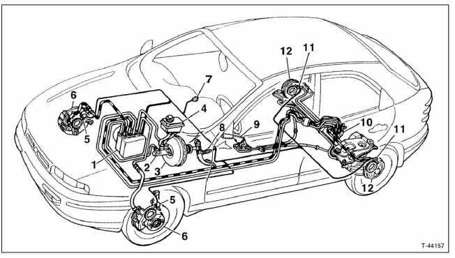
Brake system with ABS (Anti-lock Braking System)
Electro-hydraulic control unit
Master cylinder
Brake booster
Brake fluid reservoir
Wheel speed sensor, front
Disc brake, front
ABS warning lamp
Brake light switch
Handbrake lever
Brake pressure regulator
Wheel speed sensor, rear
Drum brakes, rear (except 2.0-1)
 Brake circuit right
front/rear left
 Brake circuit left
front/rear right
rear wheels. This prevents the rear wheels from locking up under braking and improves vehicle stability during braking.
The front disc brakes are fitted with a so-called single-piston floating caliper. With a floating caliper, only one piston is needed to press both brake pads against the brake disc.
The handbrake acts on the rear wheels via cables.
The disc brake pads as well as the rear drum brake shoes adjust automatically, so the rear brakes only need adjusting after repair work that involves dismantling the brake system.
Brake dust is produced when cleaning the brake system. This dust can cause health problems. Therefore, when cleaning the brake system, make sure that brake dust is not inhaled.
The brake pads are part of the general operating permit (ABE). In addition, they are matched by the factory to the specific vehicle model. It is therefore recommended to use only brake pads approved by FIAT or the Federal Motor Transport Authority (KBA). These brake pads carry a KBA approval number.
Work on the brake system requires scrupulous cleanliness and precise working methods. If you lack the necessary experience, have the brake work carried out by a qualified workshop.
Note: On roads with heavy rain, apply the brakes from time to time while driving to clear the brake discs of residue. Centrifugal force while driving throws the water off the brake discs, but a thin film of silicone, rubber abrasion, grease and dirt partly remains behind, which reduces brake response.
If the vehicle is parked after driving in the rain, especially in winter when road salt is present, it is advisable to apply the brakes beforehand with light pedal pressure until the vehicle comes to a stop. This dries the brake discs so they are less likely to corrode.
After installing new brake pads, they must be bedded in. Avoid unnecessary full braking during a driving distance of approximately 200 km.
Corroded brake discs cause a judder when braking that cannot be eliminated even by braking for a longer period. In this case the brake discs must be replaced.
Burnt-on dirt on the brake pads and clogged drainage grooves in the brake pads lead to scoring on the brake discs. This can result in reduced braking performance.
Caution: If an uneven pedal travel is noticed after cornering, check the outer diameter of the brake disc for lateral runout. If necessary, replace the brake disc.
The ABS systemDepending on model and equipment, the Fiat Bravo/Brava is fitted with an anti-lock braking system (ABS) as standard. Retrofitting the anti-lock braking system (ABS) is not possible.

The ABS consists of the electro-hydraulic control unit - 1 - with integrated electronic control module - 2 -, the ABS warning lamp, the wheel speed sensors - 3 - and sensor rings on all four wheels. 4 - Master brake cylinder.
The ABS prevents the wheels from locking during hard braking. This keeps the vehicle steerable during full braking. The driver can recognise the anti-lock control by a pulsing of the brake pedal and by noises from the hydraulic unit in the engine compartment.
A safety circuit in the electronic control module ensures that the ABS switches itself off in the event of a fault (e.g. broken cable) or if the operating voltage is too low (battery voltage below 10.5 volts). This is indicated by the ABS warning lamp lighting up on the instrument panel.
The conventional brake system remains in operation.
When braking, the vehicle then behaves as if no ABS system were fitted.
If the ABS warning lamp on the instrument panel lights up while driving, observe the following points:
Stop the vehicle briefly, switch off the engine and restart it.
Check the battery voltage. If the voltage is below 10.5 volts, charge the battery.
Check that the battery terminals are tightened correctly and make proper contact.
Raise the vehicle, remove the wheels and check the electrical wiring to the wheel speed sensors for external damage (chafe points). Further ABS checks should be left to a workshop.
Test yourself
A quick Fiat Bravo quiz: every answer comes with an explanation and a link to the manual page.