Fuel Pump Electrical Circuit Check
PROCEDURE
For more detailed information on the fuel pump circuit diagram, refer to the Electrical Systems chapter.
1. If the fuel pump does not operate when the ignition is turned on (no characteristic sound is heard from the fuel tank), check the condition of the fuel pump fuse (No. 1) or the ACG S fuse (both 15 A) in the underhood fuse/relay box. If necessary, replace the blown fuse and repeat the check. If the pump starts operating after the fuse is replaced, check the wiring of its circuit for signs of a short circuit between the PGM-FI relay and the pump.
The models covered in this Manual are equipped with a special engine start enable circuit, which supplies power to terminal No. 2 of the main relay only when the clutch pedal is depressed (MT) or the selector lever is in the “P” position (AT). This circuit is protected against overload by a dedicated 7.5 A fuse. Check the condition of fuse No. 13 in the underhood fuse/relay box.
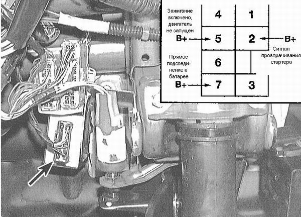
2. If replacing the fuses does not restore pump operation, check the electrical circuit of the main relay.
The main relay is mounted on a bracket installed under the instrument panel, to the left of the steering column. Ask an assistant to turn the ignition on and off several times, and check battery voltage supply to the relay connector (see accompanying illustration).
3. With the ignition off, voltage should be present at connector terminal 7. Terminal 5 should have voltage only with the ignition on (do not start the engine), while terminal 2 should be powered only when the clutch pedal is depressed (MT models) or the selector lever is in the “P” position (AT models).
4. If voltage is absent, check the circuit between the relay and the PCM. Otherwise, verify that the relay itself is functioning properly.
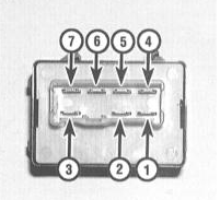
5. Using a jumper wire, connect the positive battery terminal to terminal 2, and ground terminal 1. Using an ohmmeter, check for continuity between terminals 4 and 5. If there is no continuity, replace the relay.
6. Now apply battery voltage to relay terminal 5, and ground terminal 3. Continuity should now exist between terminals 6 and 7. Otherwise, replace the relay.
7. If continuity exists, apply voltage to terminal 6, ground terminal 1, and check continuity between terminals 4 and 5. If there is no continuity, replace the relay. Otherwise, check the circuit between the fuse, the relay and the pump.
8. If the cause of pump failure cannot be identified by the checks above, verify voltage supply to the fuel pump assembly in the fuel tank. If voltage is supplied correctly, replace the fuel pump/fuel level sender assembly (see Fuel Pump Removal and Installation).
Test yourself
A quick Honda Accord quiz: every answer comes with an explanation and a link to the manual page.