Removal and Installation of Vacuum Brake Booster Assembly
REMOVAL
PROCEDURE
1. The vacuum brake booster unit cannot be repaired. If it fails, it must be replaced as an assembly.
2. Remove the master cylinder assembly from the vacuum booster (refer to Master Cylinder Removal and Installation).
3. On models with a manual transaxle, remove the clutch master cylinder (refer to Clutch and Drive Shafts Section).
4. Disconnect the vacuum hose running from the engine to the booster. Be careful not to damage the hose when removing it from the fitting on the booster assembly.
5. On 4-cylinder models, remove the intake air temperature (IAT) sensor (refer to Engine Control Section).
6. Under the instrument panel, locate the connection of the booster pushrod to the brake pedal.
7. Remove the cotter pin and disconnect the pushrod from the pedal.
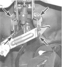
8. From the passenger compartment, remove the four nuts securing the booster assembly to the dash panel and remove the washers (use a flashlight if necessary).
9. Go to the engine compartment and remove the rear dash panel booster assembly. After the booster mounting studs have fully cleared the holes in the dash panel, begin rotating the assembly to the right (toward the vehicle centerline) to free the pushrod tip from the panel. Remove the assembly from the engine compartment.
INSTALLATION
PROCEDURE
1. Install in the reverse order of removal. Make sure all fasteners are tightened to the specified torque, and replace all pins and cotter pins.
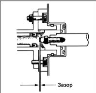
2. When installing a new brake booster, adjust the working clearance of its pushrod as follows:
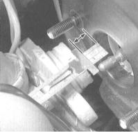
a) Using a hand vacuum pump, apply a vacuum of 508 mm Hg to the booster, then measure the protrusion of the pushrod beyond the booster surface that mates with the master cylinder (including the gasket, if one is used). Record the result as "Dimension A".
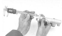
b) Measure the distance from the master cylinder mounting flange to the end face of the cylinder. Record the result as "Dimension B".
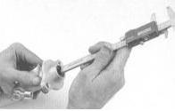
c) Measure the distance from the end face of the master cylinder to the bottom of the seat recess in the end of its piston. Record the result as "Dimension C".
d) Subtract Dimension B from Dimension C, then subtract Dimension A from the resulting difference. The final result is the required working clearance.
e) Compare the result with the Specifications. If necessary, make the appropriate adjustment.
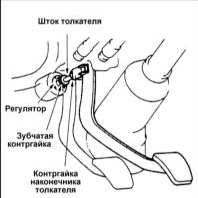
3. To adjust the pushrod working clearance, loosen the serrated lock nut and turn the adjuster in the appropriate direction. After adjustment, tighten the lock nut and measure the clearance again. Repeat the procedure if necessary.
4. After installing the master cylinder, bleed the brake system (refer to Brake System Bleeding).
Test yourself
A quick Honda Accord quiz: every answer comes with an explanation and a link to the manual page.