Automatic Transmission Control Mechanism
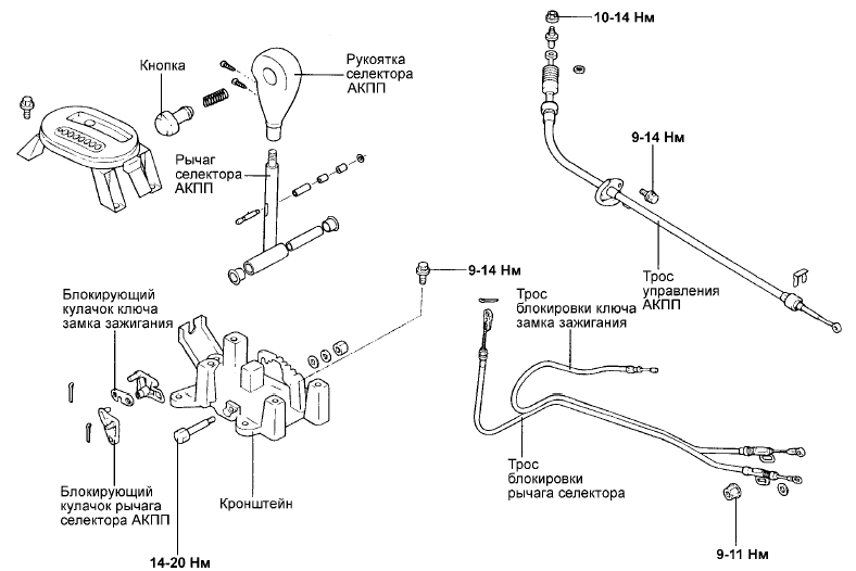
AUTOMATIC TRANSMISSION SHIFT LOCK MECHANISM - COMPONENTS
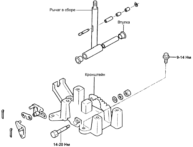
AUTOMATIC TRANSMISSION SHIFT LOCK MECHANISM - COMPONENTS
INSPECTION
• Check the stoppers and cam stoppers for wear.
• Check the automatic transmission shift lever bushings for wear or damage.
• Check the spring for damage or wear.
• Check the rod end assembly for wear.
1. Shift Lock Cam Installation Procedure
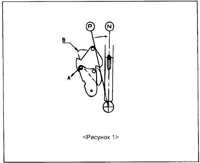
a. Move the automatic transmission shift lever lock cam in direction "A" and hold it in this position by hand (see Figure 1).
b. Check that the ignition key lock cam is in position "B" and held by the stop pin.
2. Shift Lock Cable and Ignition Key Lock Cable Adjustment Procedure
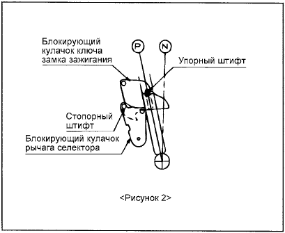
a. Check that both lock cams are set to the position shown in Figure 2.
b. Set the shift lock cable and the ignition key lock cable to the specified position. The other end of the ignition key lock cable must be secured in the ignition lock, and the shift lock cable must be secured to the brake pedal in the corresponding position.
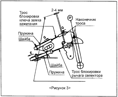
c. Temporarily connect both cables to the automatic transmission shift lever, as shown in Figure 3.
Securely attach each cable to the pin of the corresponding lock cam.
d. Lightly pull the shift lock cable in direction "E" to remove cable slack and create a clearance of 2 - 4 mm between the ignition key lock cam and the automatic transmission shift lever lock cam.
If the specified clearance is not within the range of 2 - 4 mm, the brake pedal must be depressed further than required to allow the shift lever to move to another position with the shift lock button pressed.
e. Check that the end of the shift lock cable contacts the shift lever lock cam pin, then secure the outer cable sheath to the bracket with the nut, and secure the cable end with the washer and cotter pin (see Figure 4).
f. Lightly press the ignition key lock cam in direction "Q".
g. While performing step (f), lightly pull the ignition key lock cable in direction "G" to tension the cable, then secure the outer cable sheath with the nut (see Figures 3, 4).
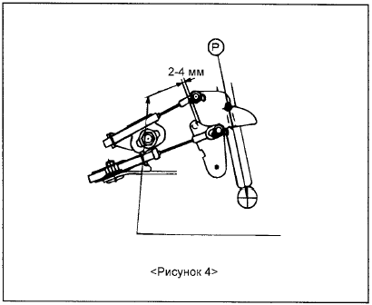
h. Make sure the end of the ignition key lock cable is seated on the ignition key lock cam pin, then secure it with the washer and cotter pin. Check that the shift lock cable is attached to the shift lever lock cam, as shown in Figure 4.
3. Shift Lock Installation Check Procedure
a. When the shift lever is in position "P" and the brake pedal is released, the shift lock button on the lever must not be pressed (the shift lever must not move from "P" to another position). The shift lock button can be pressed in all other shift lever positions (except "P").
b. If the brake pedal is depressed (pedal travel within 15 - 25 mm) when the shift lever is in position "P", the shift lock button must operate without restriction and the shift lever must move smoothly from "P" to another position.
c. If the brake pedal is released, the shift lever must move smoothly, without binding, from any other position to position "P".
d. The brake pedal must move smoothly through its full range of travel, without binding.
e. When the ignition key is in position "LOCK", the shift lock button on the shift lever must operate even when the brake pedal is released.
f. The ignition key must not turn to position "LOCK" when the shift lever is in any position other than "P".
g. When the shift lever is in position "P", the ignition key must turn to position "LOCK" without binding.
4. Maintenance Notes
a. Lightly pull the shift lock cable in direction "E" to create a clearance of 2 - 4 mm between the ignition key lock cam and the automatic transmission shift lever lock cam, then secure the outer cable sheath to the bracket with the nut. After that, check that the clearance is within the range of 2 - 4 mm.
If the specified clearance is not within the range of 2 - 4 mm, the brake pedal must be depressed further than required to allow the shift lever to move from position "P" to another position.
b. Check that the ignition key lock cable has no slack.
If the ignition key lock cable has slack, the ignition key cannot be removed from the ignition lock cylinder, and the shift lever may move from position "P" to another position even when the ignition key is in position "LOCK".
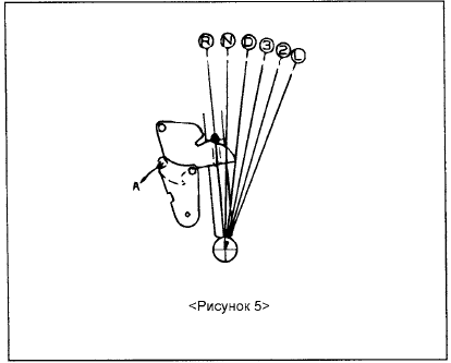
c. Before and after performing these procedures, the ignition key lock cam and the shift lever lock cam must not be in the same position, as shown in Figures 5 and 6.
If the ignition key lock cam and the shift lever lock cam are in the same position, as shown in Figures 5 and 6, forcing the shift lever from "D", "3", "2", "L" to "P", "R", "N" may damage the related components.
In the condition shown in Figure 5, move the shift lever from "D", "3", "2", "L" to "P", "R", "N" after turning the ignition key lock cam in the direction indicated by arrow "A".
Under the conditions shown in Figure 6, move the A/T selector lever from "D", "3", "2", "L" to "P", "R", "N" after turning the selector lever locking cam in the direction indicated by arrow "A", with the brake pedal depressed.
Test yourself
A quick Hyundai Elantra CN7 quiz: every answer comes with an explanation and a link to the manual page.