Electric Wastegate Actuator (EWGA)
Specifications
Specification
| Item | Specification | |
| Motor , |
Supply Voltage (V) | 13,5 |
| Supply Voltage Range (V) | 9 - 16 | |
| Max. Current (A) | < 8,5 | |
| Type | DC motor | |
| Sensor | Type | Hall effect, non-contact |
| Supply Voltage (V) | 4,9 - 5,1 | |
| Pin | 6 | |
Description and Operation
Description
The electric WGT actuator, installed on the turbocharger, controls the waste gate valve (WGT) in the turbocharger and regulates the amount of boost pressure using the PWM signal from the ECM. This actuator consists of a DC motor that drives the valve, a two-stage reduction gear that increases the DC motor torque, a position sensor that detects the valve status, and an electronic control unit that controls the DC motor.
Circuit Diagrams
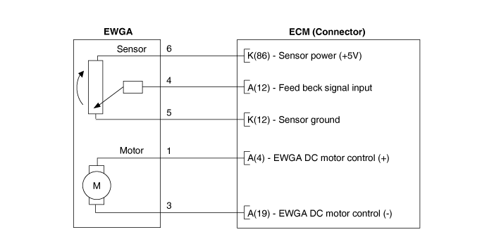
Wiring Diagram
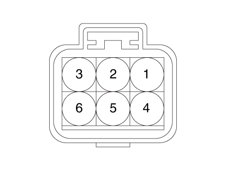
Harness Connector
Repair Procedures
Removal and Installation
Turn the ignition switch OFF and disconnect the negative (-) battery terminal.
Remove the air cleaner assembly.
(Refer to Engine Mechanical System - "Air Cleaner")
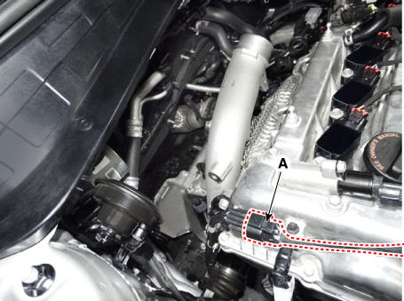
Disconnect the EWGA extension connector (A).
Remove the intake pipe bracket (A).
Tightening torque:
M8 bolt: 18.6–24 N·m
M10 bolt: 29.4–34 N·m
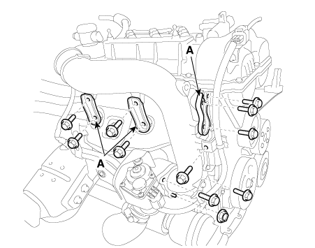
Remove the intake pipe (A).
Tightening torque:
Bolt: 29.4–39 N·m
Nut: 35.3–41 N·m
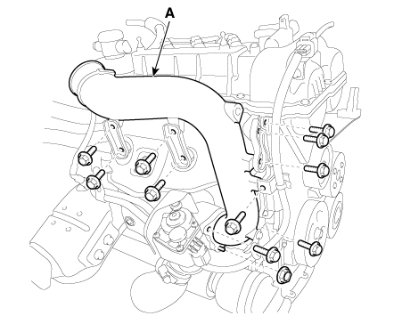
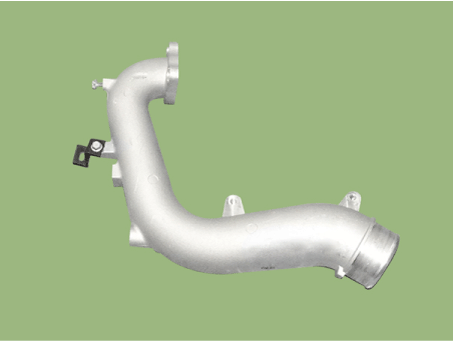
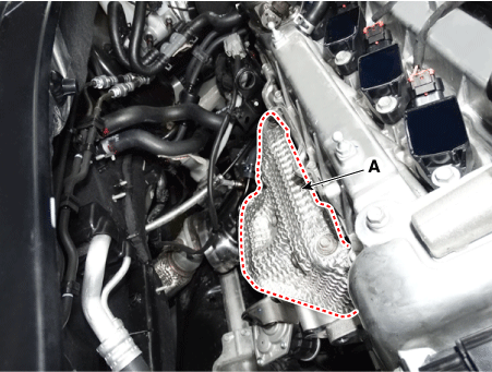
Remove the heat shield (A) after loosening the mounting bolts.
Heat shield mounting bolt: 9.8–11.8 N·m
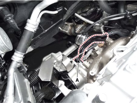
Remove the water pipe and turbocharger hose (A).
Tightening torque:
Flange bolt: 9.8–11.8 N·m
Eye bolt: 26.4–32 N·m
Disconnect the link shaft (A) by removing the C-clip (B).
Remove the electric wastegate actuator by loosening the bolts (C).
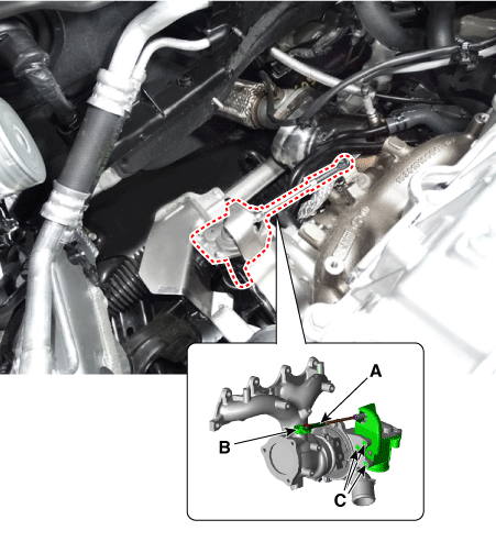
Installation is the reverse of removal.
Adjustment
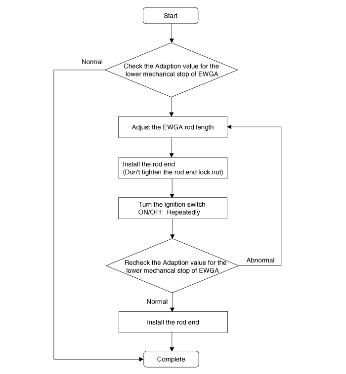
[Rod Adjustment Procedure Flow Chart]
Make sure the turbocharger wastegate valve has cooled sufficiently before working on it.
Turn the ignition switch to the OFF position.
Connect the diagnostic tool to the DLC (16-pin) connector under the driver's side instrument panel.
Turn the ignition switch to the ON position.
Select VIN or Vehicle on the initial screen.
Enter the Engine Control menu after selecting the vehicle information (Vehicle Model, Model Year, Engine Type) or entering the VIN.
Access KDS Engine > Current Data.
Without starting the engine, turn the ignition ON for 5 seconds, then turn it OFF for 5 seconds, then check the "EWGA Lower Mechanical Stop Adaptation Value" on the KDS.
Repeat this step until the change in the adaptation value compared to the previous cycle is less than 0.05 V.
Make sure the "EWGA Lower Mechanical Stop Adaptation Value" is within the specified voltage.
Voltage: 3.5–3.7 V
If the measured voltage is not within the specified voltage, adjust the EWGA rod length. If it is within the specification, no further procedure is required.
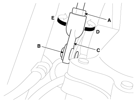
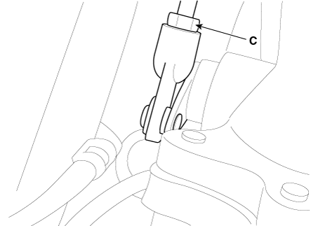
Loosen the rod end lock nut (A) and remove the C-clip (B).
Adjust the rod end (C) by turning it clockwise (D) or counterclockwise (E) to meet the specification.
For example, if the engine coolant temperature is below 25 °C, adjust as follows.
EWGA Lower Mechanical Stop Adaptation Value (V) Rod end adjustment direction Change in rod length (after adjustment) > 3,7 counterclockwise longer < 3,5 Clockwise shorter
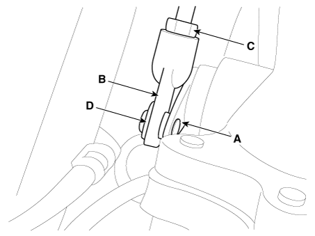
Temporarily install the rod end (B) onto the turbocharger lever (A). Do not tighten the rod end lock nut (C) and the C-clip (D).
Check the "EWGA Lower Mechanical Stop Adaptation Value" after selecting the Current Data menu.
Turn the ignition ON and OFF several times until the "EWGA Lower Mechanical Stop Adaptation Value" changes by less than 0.05 V.
If the measured voltage is not within the specified voltage, repeat steps 9 to 12 until the voltage is within the specified voltage.
Make sure the "EWGA Lower Mechanical Stop Adaptation Value" is within the specified voltage.
If it is within the specified voltage, install the rod end onto the turbocharger lever.
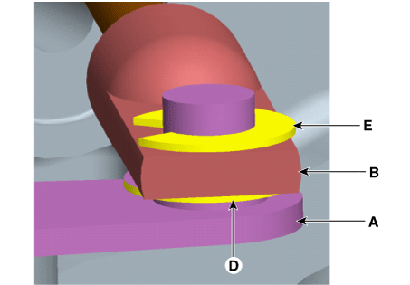
Install the rod end (B) onto the turbocharger lever (A).
Tighten the rod end lock nut (C).
Install the C-clip (E).
Test yourself
A quick Kia Forte BD quiz: every answer comes with an explanation and a link to the manual page.