Audio Remote Control
Components and Component Location
Components
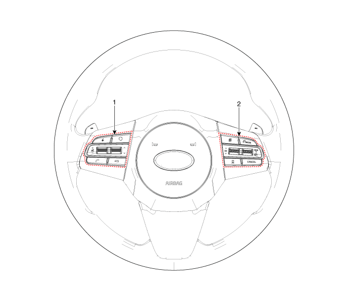
| 1. Left Remote Control Switch (Audio + Bluetooth + Voice) |
2. Right Remote Control Switch (Trip Computer + ACC + SCC) |
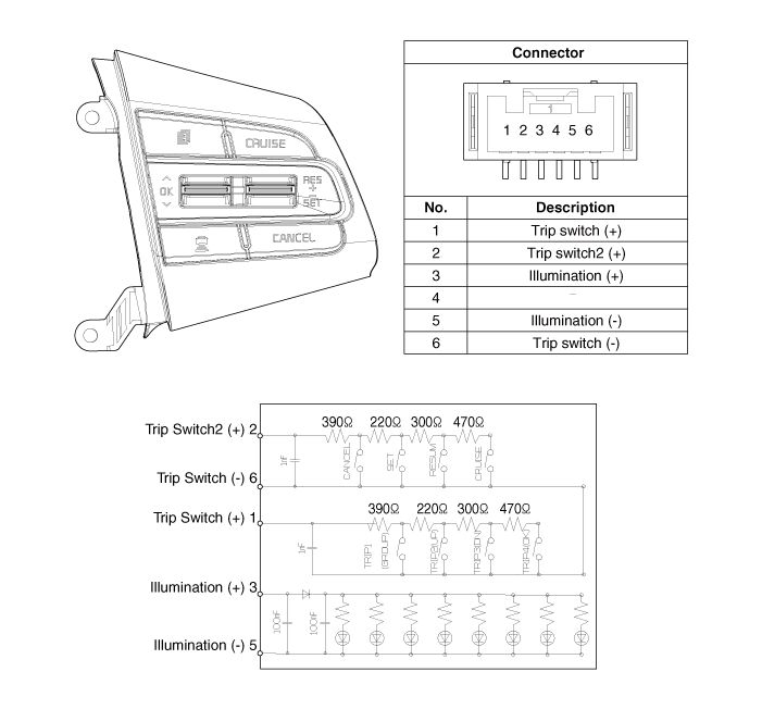
Circuit Diagrams
Wiring Diagram
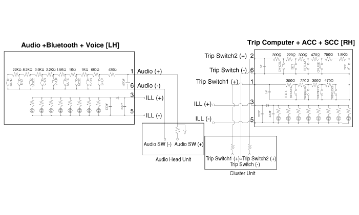
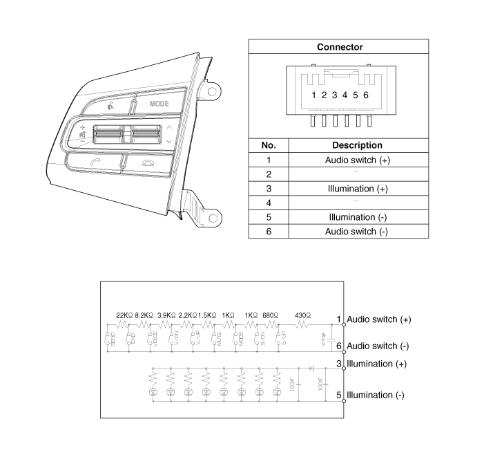
[Audio + Bluetooth + Voice]
[Trip + ACC]
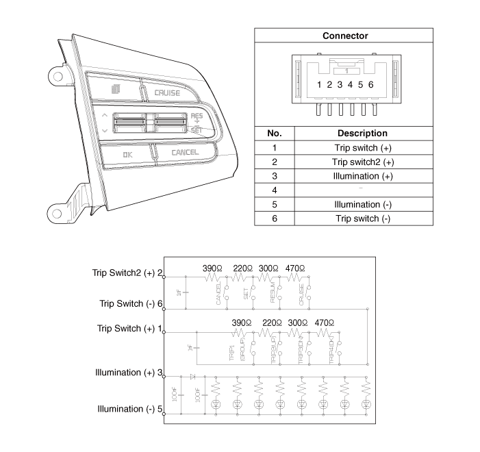
[Trip + ACC + SCC]
Repair Procedures
Removal
Disconnect the negative (-) battery terminal.
Remove the steering wheel assembly.
(Refer to Steering System - "Steering Wheel")
Remove the steering wheel switch (A) after loosening the mounting screws.
[LH]
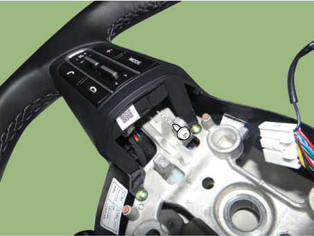
[RH]
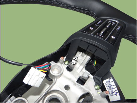
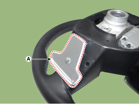
Disconnect the connector of the steering wheel switch (A).
[LH]
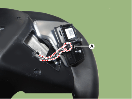
[RH]
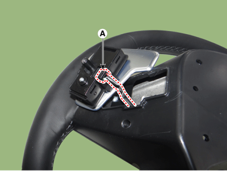
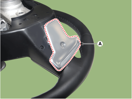
Remove the steering wheel front cover (A) after loosening the mounting screws.
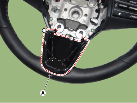
Remove the steering wheel rear cover (A) after loosening the mounting screws.
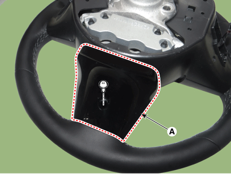
Remove the steering wheel rear cover (A) after loosening the mounting screws.
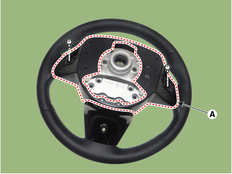
Disconnect the remote control connector on the steering wheel (A).
[LH]
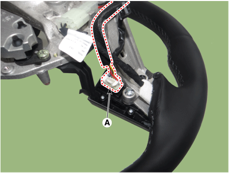
[RH]
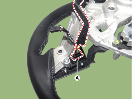
Remove the remote control switch from the steering wheel (A) after loosening the mounting screws.
[LH]
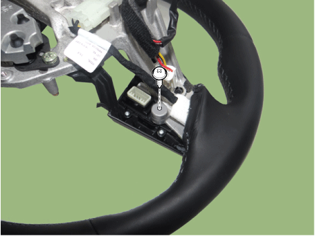
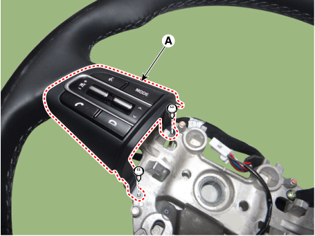
[RH]
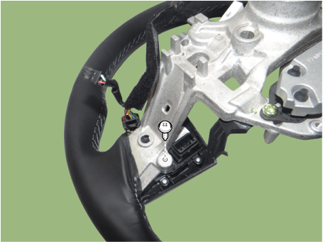
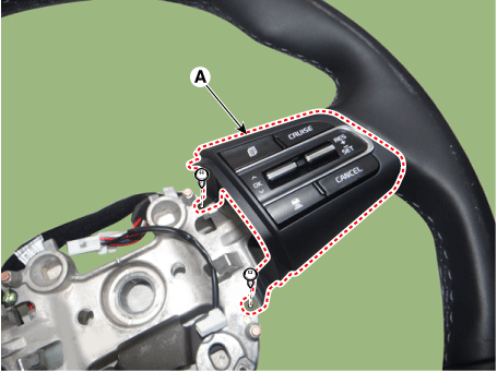
Installation
Install the remote control switch on the steering wheel.
Connect the remote control switch connector on the steering wheel.
Install the steering wheel rear cover.
Install the steering wheel rear cover.
Install the steering wheel front cover.
Connect the steering wheel switch connector.
Install the steering wheel switch.
Install the steering wheel assembly.
Connect the negative (-) battery terminal.
Inspection
Check the resistance between terminals at each switch position (LH).
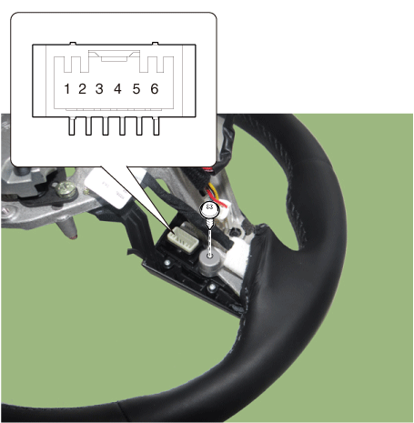
[L: Audio + Bluetooth + Voice]
Switch Connector
TerminalResistance
(±3%)SEEK UP 1-6 430 Ω SEEK DOWN 1.11 kΩ MODE 2.11 kΩ MUTE 3.11 kΩ VOL (+) 4.61 kΩ VOL (-) 6.81 kΩ Voice 10.71 kΩ END 18.91 kΩ SEND 40.91 kΩ Check the resistance between terminals at each switch position (RH).
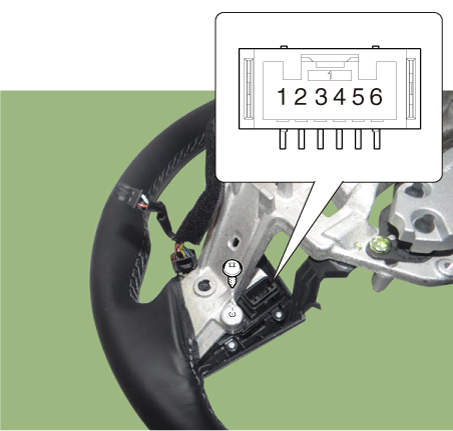
[R: Trip + ACC + SCC]
Switch Connector
TerminalResistance
(±3%)Cancel 2-6 390 Ω SET - 610 Ω VOICE + 910 Ω CRUISE ON/OFF 1.38 kΩ Cruise and Speed Limiter ON/OFF 2.13 kΩ SCC (Smart Cruise Control) 3.63 kΩ GROUP 1-6 390 Ω STEP 610 Ω TRIP DOWN 910 Ω ENTER 1.38 kΩ
Test yourself
A quick Kia Stinger CK quiz: every answer comes with an explanation and a link to the manual page.