Around View Monitor (AVM)
Components and Component Location
Components
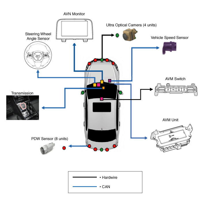
Component Functions
| No. | Components | Quantity | Main Role |
| 1 | AVM Unit | 1 |
|
| 2 | Ultra wide-angle camera (190 degrees) |
4 |
|
| 3 | AVN Head Unit | 1 |
|
| 4 | AVM Switch | 1 |
|
Description and Operation
Description
The Around View Monitor (AVM) system provides 360-degree video surveillance around the entire perimeter of the vehicle. The system consists of 4 ultra-wide-angle cameras installed around the vehicle (front, both sides, and rear).
Distortion compensation, viewpoint conversion, and video merging technologies are applied to the video images from these cameras to produce a bird's-eye view image of the area around the vehicle, as well as various other viewing modes.
The AVM system provides video of the area around the vehicle to the driver while parking or while driving at low speed, to improve driver safety and convenience.
In addition, it is equipped with synchronized guide line display on the steering wheel, front and rear obstacle warning, and A/S tolerance compensation (including In-Line).
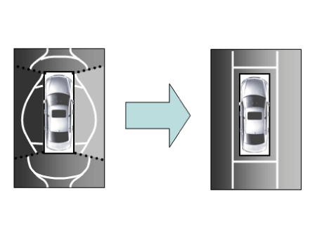
This system displays video images from the ultra-wide-angle cameras installed on the 4 sides of the vehicle on the head unit screen. It shows a 360-degree bird's-eye view of the area around the vehicle, as well as various other viewing modes.
Main Specifications
Surrounding Area Video Display of the Vehicle
The surround video display function displays a 360-degree video image captured by the four cameras on the head unit screen when the vehicle moves at low speed or in reverse. The AVM system displays a total of 8 surround video display modes depending on the vehicle motion state and driver selection.
Guide Line Display and Steering Wheel Synchronization Function
The guide line display and steering wheel synchronization function assists the driver during parking by synchronizing the steering wheel with the rear view video display marked with guide lines, helping to predict the direction of travel of the vehicle when reversing.
Front/Rear Object Warning (Obstacle Detection Function)
The system receives obstacle warning signals from the PDW or PA sensors installed at the front/rear of the vehicle and displays the obstacle location on the AVN head unit screen.
Tolerance Compensation (Including A/S)
Manual tolerance compensation software is built into the AVM ECM to compensate for AVM deviation that may occur due to assembly line installation tolerance. You must first set up the proper working environment to perform correct tolerance compensation.
Main Specifications
| No. | Main Specifications | Detailed Description | Notes |
| 1 | 8 Display Viewing Modes |
|
Combined 8-mode video image |
| 2 | Front Assist Mode Selection Function |
|
Same as AVM PDW switch |
| 3 | Synchronized Parking Guide Line Display with Rear Steering |
|
Overlay Display on Rear Video |
| 4 | PDW Obstacle Display |
|
Display on both the cluster and the head unit |
| 5 | User Setting Option |
|
Provides additional screen settings |
| 6 | Assembly Line and A/S Tolerance Compensation Function |
|
Compensation function recognition logic applied |
AVM Mode Entry Conditions
Vehicle information is accessed regularly, even after entering AVM mode. When the conditions are met, switching from front mode to rear mode and vice versa is possible.
When switching modes, the displayed view on the screen may be the initial view or the previous view, depending on the conditions.
If the switching mode is an initial entry, the default view based on front or rear is selected. If continuous front-rear switching occurs, such as repeated forward and reverse movement for parking, the previous view is recalled and displayed.
Initial entry: when the rear and front view modes in AVM mode are displayed on the screen for the first time.
Re-entry: When switching from AVM mode to another mode, without turning off AVM, and returning to the previous mode.
(e.g., rear → front → rear: re-enter rear/front mode; front → rear → front: re-enter front mode)
| Switching Mode | Vehicle Speed | Mechanism | AVM Switch | Display View |
| Rear → Front | Below 20 km/h | R range or P range excluded | ON | Initial Entry: front view is set in the initial view mode option. |
| Re-entry: the last view mode displayed in the previous front mode. | ||||
| Front → Rear | Not applicable | Reverse Gear | Not applicable | Initial Entry: rear view is set in the initial view mode option |
| Re-entry: the last view mode displayed in the previous rear mode. |
AVM Mode Exit
If the conditions below are met in AVM mode, AVM turns off and no video is displayed.
| OFF mode | Vehicle Speed | Mechanism | AVM Switch | Notes |
| Front mode | More than 20 km/h | R range or P range | OFF | If any one of the three conditions is met |
| Rear mode | Not applicable | Except R gear | Not applicable | If any one of the two conditions is met |
AVM Options
For user convenience, the AVM provides three options for the user to select from.
The option change window (parking guide settings) is displayed on the AVN. Only the changed options are sent to the AVM unit via M_CAN.
These three options apply as soon as they are selected by the user. Based on the conditions, the initial displayed views are as follows.
| Option | Function | Default settings |
| Steering Lock | Steering lock guide lines to show the vehicle's direction of travel during parking. | Classification code |
| Close Distance Warning Indicator | Indicates obstacle detection at the front and rear | Classification code |
| Initial View Mode Setting | Default view displayed when entering AVM mode | Front view + surround view |
| Rear view + Around view |
Steering Wheel Lock Guide Indication Operations
The steering wheel lock guide traces are specified using the steering wheel angle value, periodically received by the AVM unit over the C-CAN bus.
Rear area combination that displays the 130-degree rear view image (split mode) and the expected vehicle travel path shown on the wide screen.
View Modes for Steering Lock Guide Display
Mode View Application Area Notes Rear Surround View + Rear View Rear Image (Split Mode) 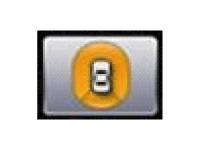
Left Rear + Rear Rear Image (Split Mode) 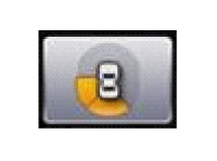
Right Rear + Rear Rear Image (Split Mode) 
Rear Wide View Wide-Screen Image 
Steering Lock Guide Line Specifications
Description Number Range Color Steering Wheel Lock Trace Lines ① 0.5 m Red ② 1.0 m Yellow ③ 3.0 m Yellow ④ Vehicle left side + 0.3 m Red + Yellow ⑤ Vehicle right side + 0.3 m Red + Yellow Neutral Trace Line ⑥ 3.0 m Blue Mode Trace Lines Around Views ⑦ Around view + 0.3 m Yellow ⑧ Yellow
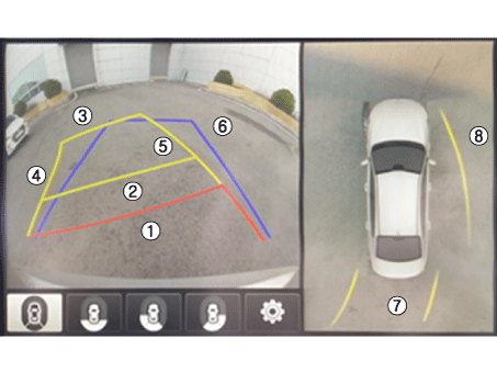
Circuit Diagrams
AVM System Input/Output
Camera Input
Item Specification Lens Viewing Angle 190 degrees Viewing Angle Horizontal 186 degrees Vertical 135 degrees Function Provides the original wide-angle image
(without additional function)Application Location The same camera is used for front, rear, left, and right AVM Image Output
The AVM unit compensates for distortion and combines the video from four cameras installed around the vehicle into one image, refers to the steering guide lines and others, and outputs the image in analog form.
AVM Switch
When the switch is turned on, it is used as a control input signal that controls the front view mode.
Ignition Input
The AVM unit displays images only when IGN2 is on. When IGN2 is off, the AVM is in the OFF state and image output is restricted.
The AVM unit uses the input signal from the IGN terminal or M_CAN communication to determine whether IGN2 is on or off.
Output Switch Indicator Lamp
The AVM units send output power in the form of PWM waves to the LED located in the AVM switch to show the user that the switch is pressed.
Chassis CAN Input (C_CAN)
The AVM unit uses C_CAN to receive vehicle status information and to determine whether to perform basic AVM operations.
Multimedia CAN Input/Output (M_CAN)
The M-CAN signal is converted to a C-CAN signal by the IGPM (routing function or central gateway), and then the AVM unit can use this C-CAN signal.
M_CAN is used to communicate with the ICU to send and receive the following information.
Sends AVM mode change requests for the AVM output images (e.g., Navi mode → AVM mode)
Sends AVM view change requests from the user
Send compensation coordinates for tolerance compensation.
Sends warning messages to be displayed on the AVN
Send any changes to user parameters.
Repair Procedures
Inspection
Tolerance Compensation
Tolerance compensation corrects the surround view video errors that occur due to installation tolerances of the four cameras that make up the SVM system.
Tolerance compensation must be performed when the following actions are carried out:
When removing and installing the wide-angle camera.
When performing body work, such as work on the body that causes the focus of the wide-angle camera to change.
When replacing the door mirror with a wide-angle camera.
When replacing the surround view monitor unit.
Tolerance Compensation Environment
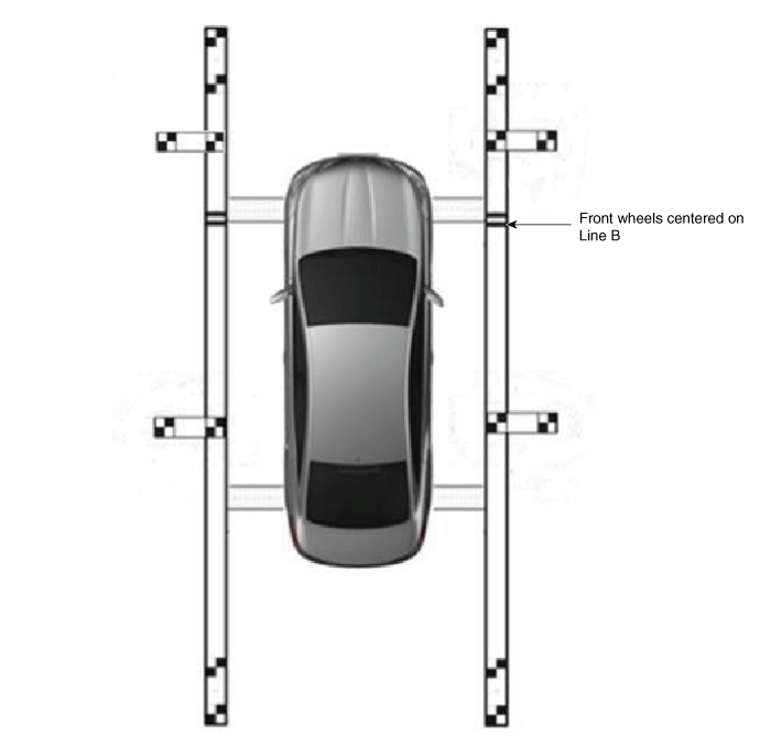
Tolerance Compensation Guide Procedure
Prepare in advance as shown below.
Make sure the hood, trunk and vehicle doors are closed.
Close the driver's door after getting in.
Turn the ignition to the "IGN" position.
Extend all side mirrors.
Shift the transmission to N.
Check the blinking status of the LED indicator lamp in the SVM switch.
During preparation, do not install an exhaust fan inhaler or other equipment that may block the view of the rear view cameras.
Also, since exhaust gas may block the rear view image, blow out smoke with a fan before performing tolerance compensation with the ignition on.
Apply the foot brake or electronic parking brake (EPB) to hold the vehicle in place.
Before entering tolerance compensation mode, check the normal operation of the SVM ECU and cameras by performing the following.
Make sure the SVM initial setting screen is displayed (front view image + surround view image when shifted to N).
Make sure the front, rear, left and right surround view monitor images are displayed correctly.
If the images are displayed correctly, enter tolerance compensation mode. Otherwise, if the images are displayed incorrectly or not displayed, replace the corresponding part.
Install two compensation scales, two compensation reference line boards, and four compensation targets around the vehicle, referring to the manual supplied with the tools.
Keep the ignition on with the vehicle stopped, make sure the transmission is in P and apply the parking brake, even on level ground.
Perform the work with SVM on.
Connect the KDS to the vehicle.
Select the vehicle model and system.
Enter the special function in the KDS.
Perform manual SVM tolerance compensation as shown on the KDS diagnostic device.
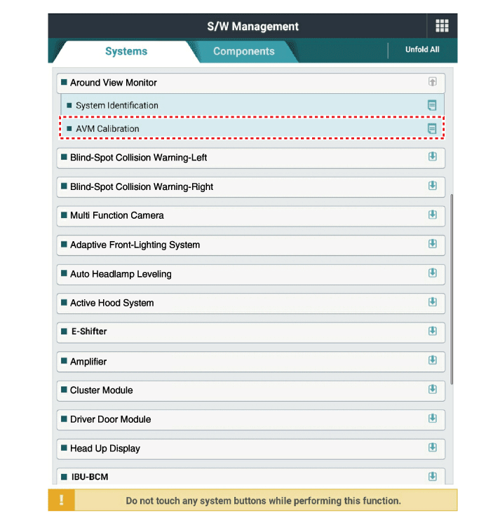

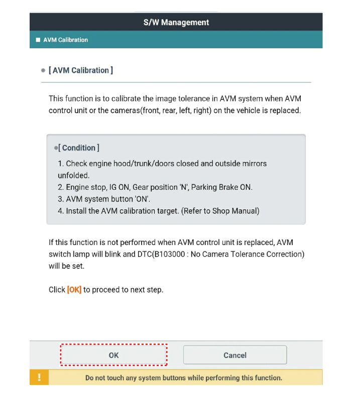
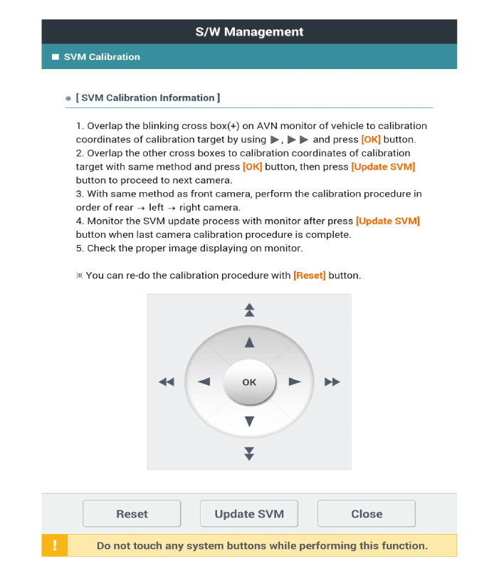
To confirm that calibration is complete, check the vehicle and calibration on the AVN monitor and press [OK].
If calibration was not performed properly, click [Cancel] and re-enter the calibration points.
Test yourself
A quick Kia Stinger CK quiz: every answer comes with an explanation and a link to the manual page.