Power Tailgate System
Components and Component Location
Components
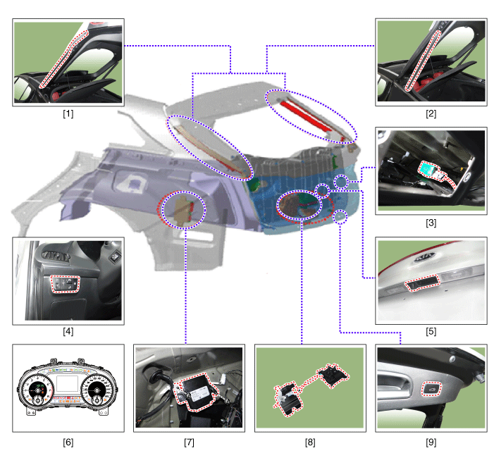
| 1. Anti-pinch strip (2 pcs) 2. Power tailgate spindle (2 pcs) 3. Power tailgate buzzer 4. Side safety panel switch 5. Outside handle switch |
6. Cluster (UCM) 7. Power Tailgate Module (PTGM) 8. Power tailgate latch and power close unit assembly 9. Power tailgate inside switch |
Description and Operation
Description
The Power Tailgate System is an electromechanical system that can open and close the tailgate automatically, using the local switch (push-button switch inside the tailgate and outside handle switch) and the wireless remote key (FOB), or it can stop the tailgate. The Power Tailgate Module (PTGM) sends and receives information via BCM, instrument cluster, SJB and CAN communication, so it can decide tailgate opening/closing and perform self-diagnosis.
There is a safety function to reverse direction when an obstacle is detected during operation.
If the power mode is disabled due to a discharged battery or the Power Tailgate Module (PTGM) is disconnected, manual opening/closing is possible using the emergency lever on the tailgate latch after unlocking the tailgate.
Power Tailgate Position and Direction
The PTG system measures the tailgate position using the Hall sensor inside the spindle assembly motor.
In addition, the tailgate direction can be confirmed by analyzing the spindle operating direction.
The Hall sensor signal count (position confirmation) is valid in both power operation mode and normal operation mode.
The PTG automatic operation mode can be changed to manual operation mode by changing the cluster settings.
Components
Power Tailgate Module (PTGM)
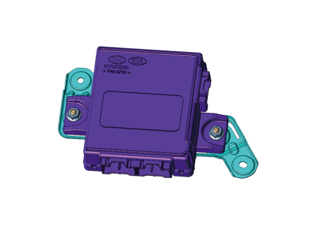
The PTGM is installed inside the right rear side trim panel.
The PTGM controls the two spindle drive motors.
It also controls the anti-pinch function by analyzing the anti-pinch sensor and the Hall sensor in the spindle.
PTG latch assembly
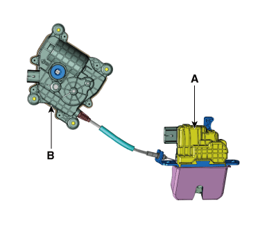
The PTG latch assembly consists of a power latch (A) and a power close device (B).
The PTG latch assembly is installed at the end of the tailgate and operates the power lock/unlock mode controlled by the PTGM.
PTG spindle
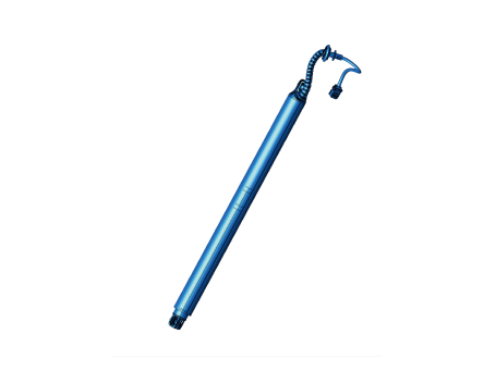
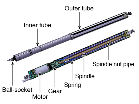
The PTG spindle opens and closes the tailgate using the torque of the internal motor.
Detect the tailgate moving direction by sending the rotation direction signal of the internal spindle motor to the PTGM.
Anti-pinch strip
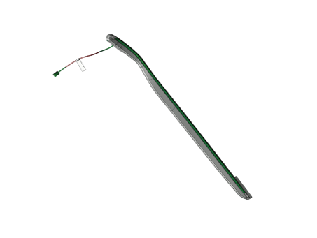
APS (Anti-Pinch Strip) is installed on the left and right sides of the tailgate and detects an object being pinched while the power tailgate is closing.
When a pinch is detected, the PTGM immediately reverses the tailgate to the fully open status.
The anti-pinch strip does not function when the tailgate is fully closed or fully open, is stationary, or is opening.
Wireless Transmitter
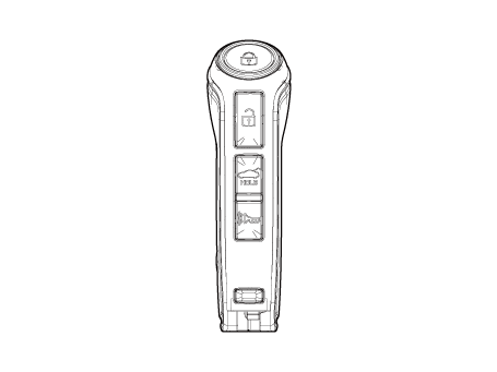
The tailgate starts the Power Opening function when the tailgate button on the wireless transmitter is pressed for more than 1.0 second.
If the button is pressed briefly while the power tailgate is opening or closing, the power tailgate will stop.
If the button is pressed for 1.0 second while the power tailgate is opening or closing, the power tailgate will change its direction.
Side Safety Panel Switch
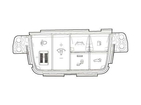
If the side safety panel switch is pressed for 1.0 second, the tailgate will operate the power opening or closing function.
If the side panel switch is pressed briefly while the power tailgate is opening or closing, the power tailgate will stop.
If the side safety switch is pressed within 1.0 second while the power liftgate is opening or closing, the power liftgate reverses its direction.
Power Liftgate Inside Switch
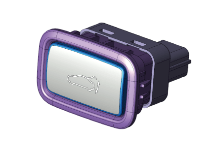
If the switch inside the liftgate is pressed, the liftgate opens. Power close function.
Power Liftgate Buzzer
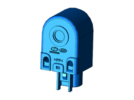
When an obstacle is detected or the power function operates incorrectly, the warning buzzer sounds 3 times according to the user's setting.
When the power function operates correctly, the warning buzzer sounds twice.
Operating Principle
Power Liftgate Open Process
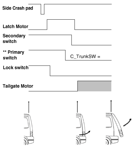
The primary switch signal is sent to the PTGM via CAN bus. (Sent by SJB)
Power Liftgate Open Process
Opening starts after signals from the liftgate emergency panel lower switch, manual switch, or wireless remote key (FOB).
The latch motor opens the liftgate by releasing the latch (via SJB).
To open the liftgate, the PTG module activates the liftgate spindle motors.
The speed of the spindle motors is controlled by the Hall sensor in the motor.
The liftgate opening angle is calculated from the number of Hall sensor pulses.
Power Liftgate Close Process
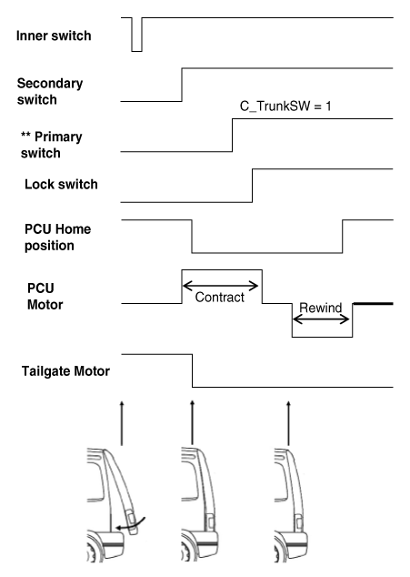
Power Liftgate Close Procedure:
Closing starts after signals from the liftgate emergency panel inside switch or wireless remote key (FOB).
To close the liftgate, the PTGM activates the spindle motors.
The PTGM monitors the liftgate closing angle by counting pulses from the Hall sensors.
The liftgate latch engages the striker, and if the closing force is not too weak, the latch will be in the Half Latch position. (Latch fully open → Latch half latch)
After receiving the Half Latch switch signal from the latch, the PTGM stops the liftgate spindle motor operation.
The PTGM supplies voltage to the PCU, and the PCU starts the locking operation until the PTGM receives the Full Latch signal from the latch.
The tailgate is fully closed and the latch is fully locked.
Learning/Calculation/Program Position

Maximum Open Position
Opening movement beyond this position will cause the liftgate to reach the maximum base position and overload the mechanical system (hinge).
Therefore, opening movement beyond this position is not possible.
However, if movement started from a lower position, the liftgate will move beyond this point.
Learned Mechanical End Position
The mechanical end position is the position of the mechanical stop, which is considered 100% open.
This position is learned during the first opening of the liftgate.
After learning, the liftgate will not travel beyond the maximum base position, which is defined as a smooth stop.
All positions will be defined by parameters that are stored in the ECU.
Open Maximum Programming (Garage Position)
After learning the mechanical end position, the base position set by the user will be considered the maximum base position.
The user can move the learned base position to any position (between the Maximum Position for Closing and the Maximum Base Position).
If the user wants to set the new base position lower than the old base position, the user must move the liftgate to the new position automatically or manually and press the liftgate inside switch for five seconds. (Time may vary depending on parameters.)
If the user sets the liftgate position higher than the maximum base position, the ECU will set the base position as the maximum base position.
System Parameter
Before guaranteeing normal operation, mechanical tolerances and adjustment on the vehicle assembly line and correction of the maximum range of motion with the Power Liftgate are required.
From the end point, which is limited by the mechanical stop when the liftgate is fully closed (latch locked), the maximum range of motion of the liftgate during operation is expressed by the number of Hall sensor pulses of the spindle rotation speed and position sensor, which are sent to the ECU.
Calibration Mode
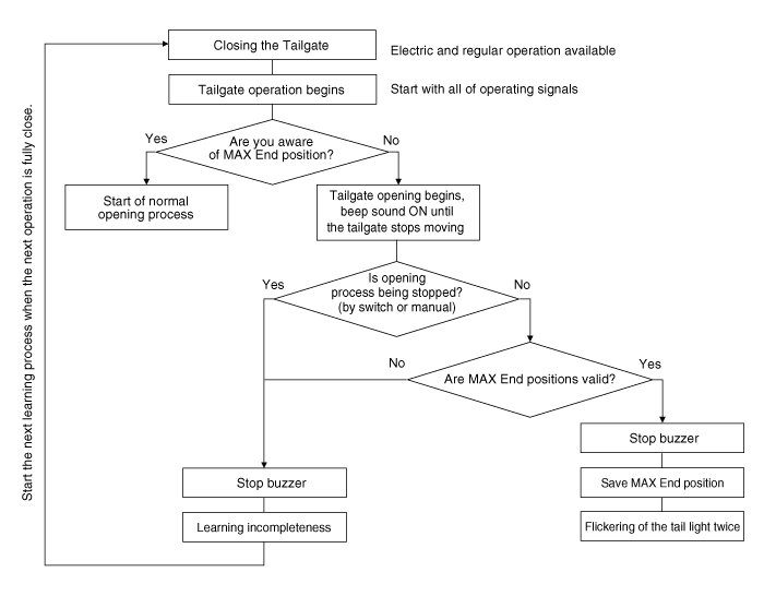
Manual Decalibration Mode
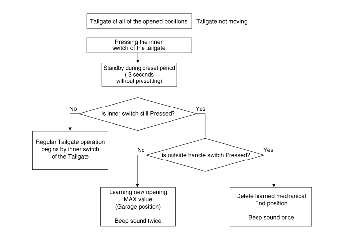
Buzzer Operation Mode
| Operation | Request source | Buzzer cycle count | Number of Hazard Cycles | Comment |
| Start Opening | Exterior switch | 2 | 2 | Liftgate start delay until the first cycle is completed |
| Interior switch | ||||
| Console Switch | ||||
| Remote Key | ||||
| Smart Key | ||||
| Start Closing | Exterior switch | 2 | 2 | |
| Interior switch | ||||
| Console Switch | ||||
| Remote Key | ||||
| Smart Key | ||||
| Direct reversal (Open -> Close) (Range: closed - maximum end point for closing) |
Exterior switch | 2 | 2 | No delay (reverse and buzzer simultaneously) - Only delay due to mechanical system |
| Interior switch | ||||
| Console Switch | ||||
| Remote Key | ||||
| Smart Key | ||||
| Obstacle detection (Start of reverse) |
- | 3 | - | - |
| Vehicle speed with tailgate open | - | 10 | - | Stop condition 1. Perform 10 times. 2. Full lock of liftgate. |
| Adjust Height | Interior switch | 2 | - | - |
| Initialization (Deletion of end position and base position) |
Interior switch and exterior switch | 1 | - | - |
| Initialization (Learning end point) |
- | - | 2 | - |
| Initialization (During calibration) |
- | Continuous | - | - |
| Tailgate not closed | - | 10 | 10 | Liftgate closed, but latch switch is not off (still open) |
| Fault Detection | - | 3 | - | - EPS error - Spindle error - Hall sensor error - System error (EEPROM error) - Voltage error (high/low) - Control unit error - Latch position error - Stuck switches (switch pressed for more than 30 seconds) - Thermal protection |
Troubleshooting
Failure Check
Diagnosis using KDS
In the body electrical system, faults can be quickly diagnosed using the Korean Diagnostic System (KDS).
The Diagnostic System (KDS) provides the following information.
Self-Diagnosis: Checks malfunction and Diagnostic Trouble Code (DTC)
Current Data: Check the system input/output status.
Actuation Test: Check the system operating status
Additional function: Control of other functions, including the setting parameter system and zero point adjustment.
Select "Vehicle Model" and "Power Liftgate Module" to check using the tester.
Select the "Current Data" menu to view the current input/output data status.
To forcibly activate the input value of the module under test, select the "Activation Test" option.
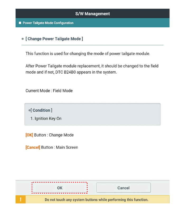
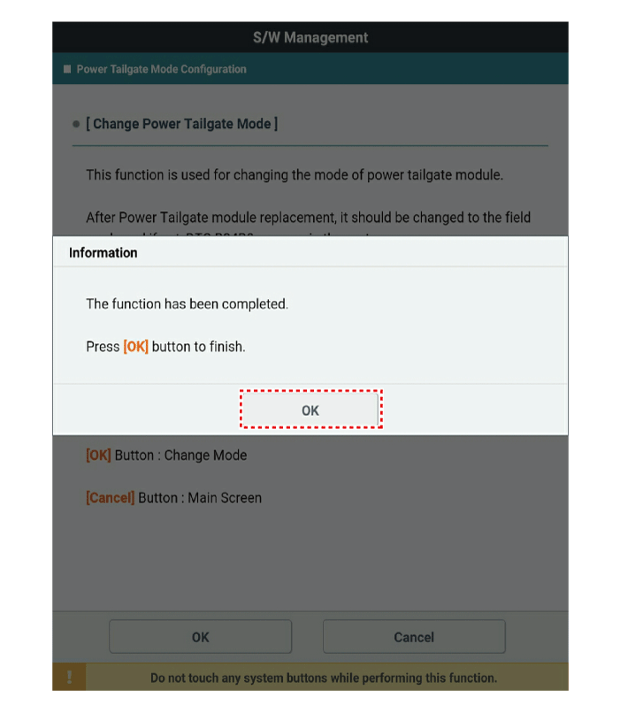
Mode Change (Power Liftgate System)
After replacing with a new power liftgate module, check for DTCs at all times.
If DTC B24B0 is present, perform the power liftgate mode change.
After connecting the KDS, select the "Power Liftgate Mode Change" procedure.
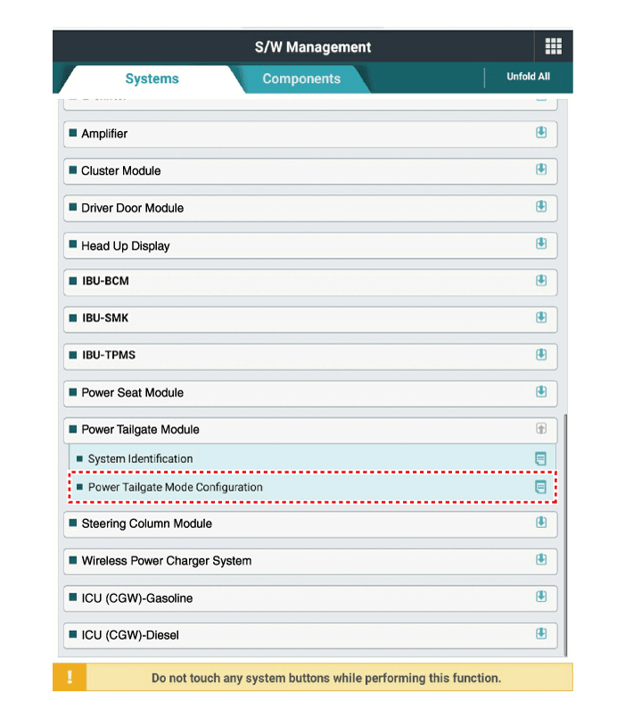
Change the tailgate mode by following the messages displayed on the KDS.
System Initialization
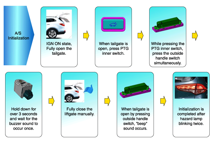
System initialization is required to recognize the closed position of the tailgate by the power tailgate module.
Initialization process after battery power reset. System initialization is required to accurately determine the maximum open and closed positions of the power tailgate.
The power tailgate operates normally after system initialization is completed.
Procedure:
Inspection and Testing - Power Tailgate System
The power tailgate system is a complex system consisting of several components. To obtain an accurate inspection result, the power tailgate control module must be inspected.
The most reliable, efficient, and accurate method is to use the KDS, which is required for the power tailgate.
The KDS assists technicians in inspecting the disconnected switch and allows checking the recorded current status of the power tailgate control module switch.
The battery must be fully charged before performing all power tailgate tests, and all interfering system elements must be identified and understood. (Refer to the Smart Tailgate description.) See the diagnostic reference table for Smart Tailgate inspection and testing.
| Status | Cause | Solution |
| Liftgate opens suddenly | Inadvertent activation or malfunction of the open/close switch | Check the switch for a short circuit or short-circuit malfunction |
| Latch assembly malfunction | Check the wiring connection | |
| Check for DTCs and replace the latch if necessary. | ||
| Smart Tailgate or Body Control Module failure | Reset the module fuse or reconnect the battery. If it does not operate properly, check the wiring connection and refer to the service manual. | |
| Liftgate cannot be opened or closed | False indication or not-parked condition | Check the switch status using the scan tool |
| Low battery voltage to Power Tailgate module | Check the voltage at the power liftgate. | |
| Battery charged | ||
| Fuse blown | Check whether the fuse is blown | |
| PTG spindle malfunction | Check the PTG spindle condition | |
| Critical Code Fault in IBU/Tailgate Control Module | Check Code Status Using KDS | |
| Latch assembly malfunction | Check whether the fuse wiring connections are blown. | |
| Check whether a foreign object is interfering with the latch assembly. | ||
| Liftgate cannot be opened or closed | Motor assembly malfunction | Check the motor assembly |
| Interference of components | Replace the necessary parts or reset the malfunctioning position. | |
| Wiring problem (system or vehicle) | Solve the problem using the wiring diagram. | |
| Refer to the wiring diagram. | ||
| Loss of power during liftgate operation | Wiring problem (system or vehicle) | Solve the problem using the wiring diagram. |
| Refer to the wiring diagram. | ||
| Low vehicle battery voltage | Check the PTGM voltage. | |
| Charge the battery. | ||
| Power Tailgate or IBU Failure | Check the DTC using the scan tool | |
| Motor assembly malfunction | Check the motor assembly | |
| Power lock not possible in primary/secondary position | Latch assembly malfunction | Check whether the fuse wiring connections are blown. |
| Check the DTC using the scan tool | ||
| Solve the problem using the vehicle diagnostic manual. | ||
| Replace the latch assembly if necessary. | ||
| Interference of components | Replace the necessary parts or reset the malfunctioning position. | |
| Power Tailgate or IBU Failure | Check the DTC using the scan tool | |
| Excessive power liftgate seal force | Check for impact on the seal, assembly malfunction, foreign objects, or other possible causes. | |
| Motor assembly malfunction | Check the motor assembly | |
| Latch cannot be unlocked in primary position | False indication or not-parked condition | Check the switch status using the scan tool |
| Low battery voltage to Power Tailgate module | Check the voltage at the power liftgate. | |
| Battery charged | ||
| Fuse blown | Check whether the fuse is blown | |
| Latch assembly malfunction | Check the switch status using the scan tool | |
| Check whether a foreign object is interfering with the latch assembly or impact on components. | ||
| Solve the problem using the vehicle diagnostic manual. | ||
| Remove the latch assembly if necessary. | ||
| Malfunction in the outside handle connection | Check the handle connection and the wiring connection. | |
| Power liftgate or Body Control Module failure | Check the DTC or perform a cycle using the scan tool. | |
| Interference of components | Replace the necessary parts or reset the malfunctioning position. | |
| Liftgate control with the pull-out/console switch is not available. | Fuse blown | Check whether the fuse is blown |
| Low PTGM voltage | Check the PTGM voltage. | |
| Charge the battery. | ||
| Power lock cannot be unlocked | Lock assembly malfunction | Check whether a foreign object is interfering with the latch assembly or impact on components. |
| Check the DTC or perform a cycle using the scan tool. | ||
| Check the "pole/latch" switch using the scan tool. | ||
| Solve the problem using the vehicle inspection manual | ||
| Power lock cannot be unlocked | Power liftgate module malfunction | Solve the problem using the vehicle inspection manual |
| Integrated Body Control Unit (IBU) Failure | Solve the problem using the vehicle inspection manual | |
| Replace the IBU if necessary. | ||
| Wireless remote control key malfunction | Reprogram the wireless remote control key | |
| Replace the wireless remote control key | ||
| Liftgate motor assembly malfunction | Check for foreign objects interfering with the motor assembly. | |
| Check the wiring connection | ||
| Replace the assembly if the motor clutch does not operate. | ||
| Replace the switch if the fully open switch does not operate. | ||
| Solve the problem using the vehicle inspection manual | ||
| Replace the motor if necessary | ||
| Liftgate cannot be held in the open position | PTG spindle failure | Replace the PTG spindle |
| Check whether the attached objects are damaged | ||
| Excessive operating force when opening and closing | PTG spindle failure | Replace the PTG spindle |
| Check whether the attached objects are damaged | ||
| Interference of components | Replace the necessary parts or reset the malfunctioning position. | |
| Liftgate keeps locking | Lock assembly malfunction | Check whether the wiring connections and fuse are blown. |
| Check the switch using the scan tool | ||
| Liftgate remains in power lock mode | Lock assembly malfunction | Check the wiring connection |
| Check for a foreign object | ||
| Solve the problem using the vehicle inspection manual | ||
| Control unit malfunction | Check the DTC using the scan tool | |
| Wiring problem (system or vehicle) | Troubleshoot the electrical circuit | |
| Refer to the wiring diagram. | ||
| For detailed procedures, refer to the Vehicle Inspection manual. | ||
| Motor assembly malfunction | Always check the operating environment | |
| Wiring problem (system or vehicle) | Troubleshoot the electrical circuit | |
| Refer to the wiring diagram. | ||
| Tailgate opens very slowly | Vehicle battery voltage is too low | Check the PTGM voltage. |
| Charge the battery. | ||
| Power tailgate spindle malfunction | If necessary, replace the power tailgate PTG spindle. | |
| Interference of components | Replace the necessary parts or reset the malfunctioning position. | |
| Vehicle incline is too steep for power operation | Operate the tailgate manually | |
| Liftgate motor assembly malfunction | If necessary, replace the motor assembly | |
| Rattling or squeaking noise | Foreign object caught in the tailgate components | Remove the foreign object |
| Excessive tightening or loosening of components | Correct excessive play or looseness |
Test yourself
A quick Kia Stinger CK quiz: every answer comes with an explanation and a link to the manual page.