Adaptive Front-Lighting System (AFS)
Specifications
Specifications
| Contents | Value | |
| AFS | Rated Voltage | 13.5 V DC |
| Maximum voltage | 16.5 V | |
| Rated Voltage | 9.5–16 V DC | |
| Operating Temperature | -22 to 167°F (-30 to 75°C) | |
| Operating Current | MAX. 200 mA | |
Components and Component Location
Components

| 1. Adaptive Front-Lighting System (AFS) Unit 2. Rear Height Sensor |
3. Headlamp (Swivel, Leveling) |
Circuit Diagrams
Wiring Diagram

Description and Operation
Description
Adaptive Front-Lighting System (AFS)
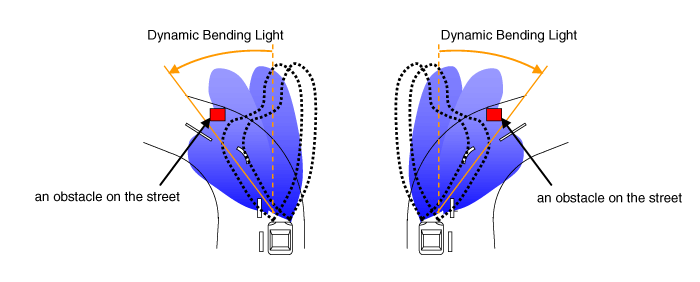
AFS (Adaptive Front-Lighting System) is a headlight aiming control system that considers both the steering wheel angle and vehicle speed to direct the headlights at an angle that provides better visibility at night.
Changing conditions make the beam pattern of a moving vehicle appear kaleidoscopic.
AFS Components
Input section: Receives information from the speed sensor, height sensor, and other sensors related to vehicle condition.
Control section (AFS unit): Controls the output section by analyzing and evaluating the input signal.
Output section: Controls the low beam H/Lamp up/down and left/right lateral optimal beam pattern by the output control signal of the AFS unit.
Main Function of AFS
| Contents | Description | |
| 1 | Dynamic Bending Light (Swivel) |
|
| 2 | Automatic Leveling (Leveling) |
|
| 3 | Fail-safe |
|
Advantages of AFS
| Contents | Description | |
| 1 | Improved Stability |
|
| 2 | Improved Convenience |
|
Block Diagram
Operation
Component
AFS Unit (A)

General
System initialization when the engine signal is received (AFS ECU, swivel motor)
AFS OFF Switch Adaptation
AFS operates normally only when the headlight switch is turned on.
Provides an AFS indicator function ("AFS" displayed on the instrument cluster).
In case of a system failure, the "AFS" indicator illuminates on the instrument cluster.
Main Function
Swivel Function
Leveling Function
Height Sensor Signal Processing
Controls the shield drum to change the beam pattern
Controls the static cornering light
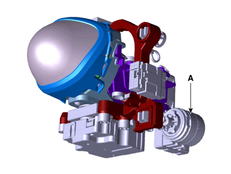
Swivel Actuator (A)

General
Communicates with the AFS unit via LIN protocol
Robust interference control
Does not operate outside the rated voltage range.
Main Function and Ratings
Low Beam Left/Right Actuation
Fail-safe function: if a malfunction or system failure is detected, move to a safe position
Leveling Motor (A)
Main Specifications
Communicates with the AFS unit via LIN protocol
Robust interference control
Does not operate outside the rated voltage range.
Main Function and Ratings
Low Beam Up/Down Actuator
Fail-safe function: if a malfunction or system failure is detected, move to a safe position
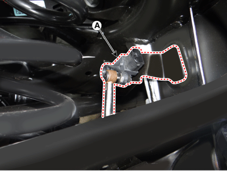
Height sensor
General
The height sensor, which connects the body and suspension, measures the tilt information according to load.
Vehicles with steel suspension transmit the tilt signal to the AFS ECU through a hard wire.
Rating
Rated voltage: 5 V ± 5%
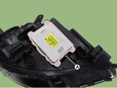
LED Headlamp, LDM (A)
LDM System Description
The LED (Light Emitting Diode) beam mainly consists of the LED module, cooling fan, and LDM (LED Driver Module).
The LED module consists of four units, and each unit consists of three LEDs. The cooling fan cools the heat generated by the LEDs.
If the fan fails, it sends a failure signal to the LDM.
The LDM is the module that controls the LEDs. The cluster warning lamp turns on or flashes if the fan or LED fails.
Repair Procedures
Inspection
Initialization and Diagnostic Sequence Using Diagnostic Equipment
The following is a summary of the A/S procedure using diagnostic equipment.
Download Parameter
Select the "AFS" menu after selecting the vehicle.
Select the "Load Parameter" menu to define the vehicle characteristics.


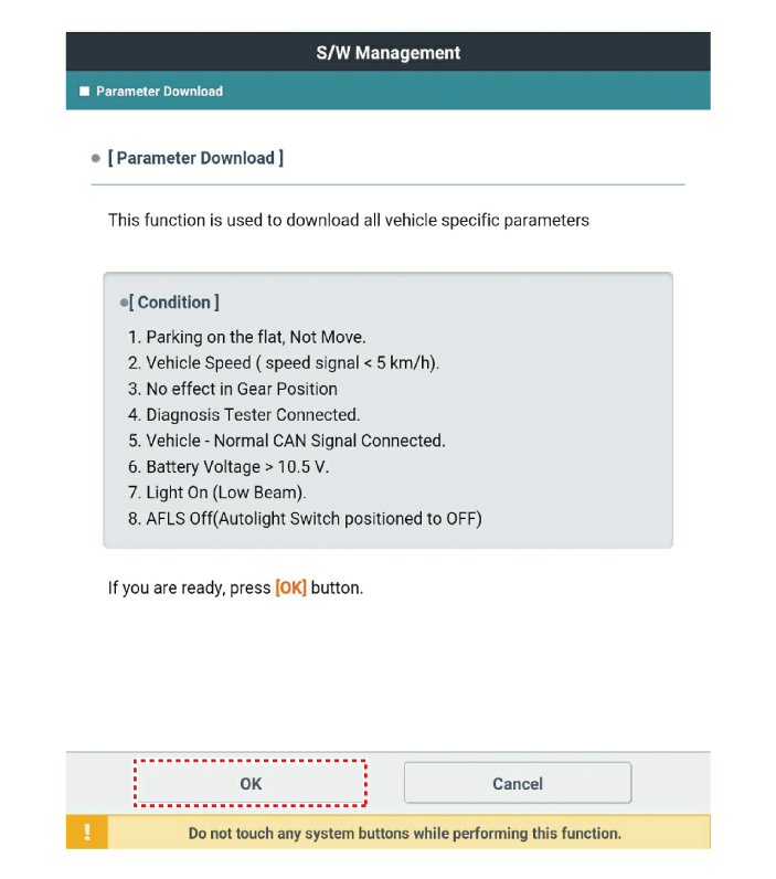

When "Download Parameter" is completed, the display appears as follows.

System Calibration
Select the "AFS" menu after selecting the vehicle.
KDS will show the steps of the AFS calibration function.

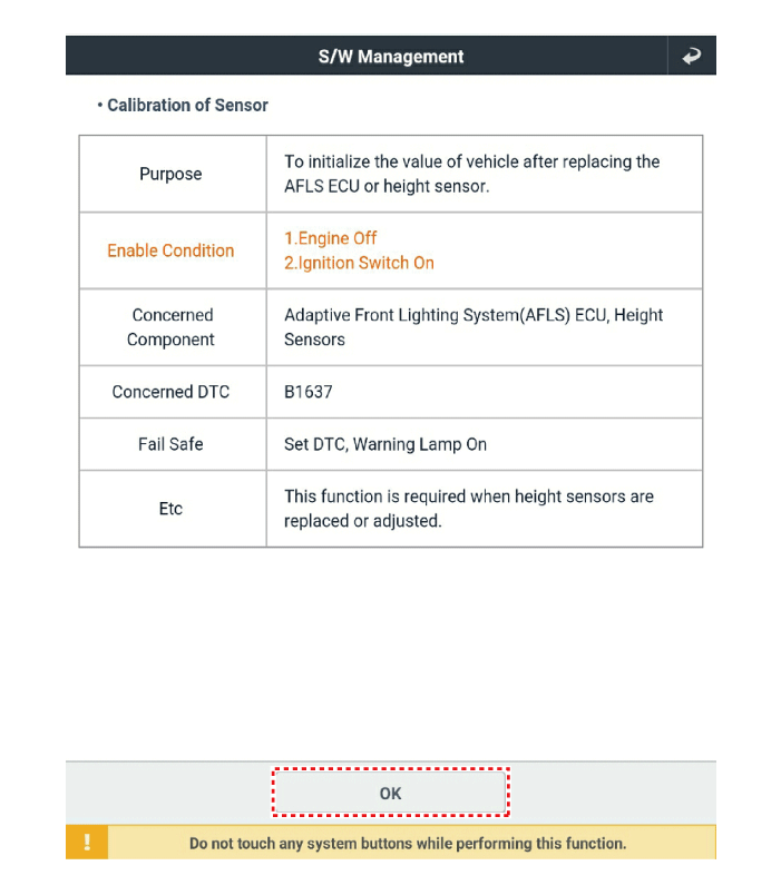
When "System Calibration" is completed, the display appears as follows.
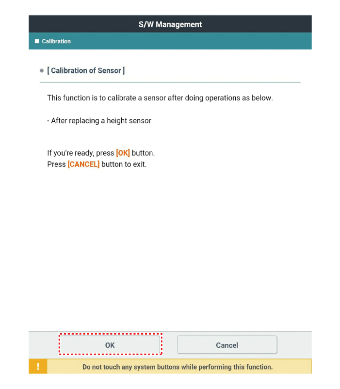
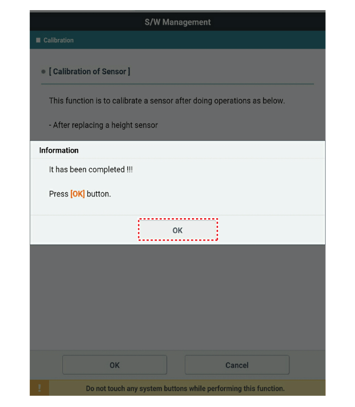
AFS Calibration Procedure
When replacing the AFS ECU, H/Lamp unit, or height sensor, perform the calibration procedure using the diagnostic equipment as described below.
When performing the AFS calibration procedure, be sure to confirm the suspension type, and then download the parameter.
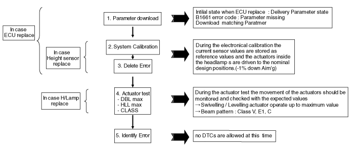
※ DTC: Diagnostic Trouble Code
DBL: Dynamic Bending Light
HLL: Headlamp Leveling
Vehicle Condition AFS Calibration
Vehicle on level surface
No vehicle movement
Gear selector in P&N
Ignition ON and engine speed >500 rpm
Diagnostic equipment connected
ALL ECUs on CAN installed and activated
Battery voltage > 10.5 V (ECU power supply must be ensured)
Light OFF
AFS ON or OFF
Actions When Invalid Parameter Is Downloaded
Download delivery parameter
Check B1661 (parameter missing)
Ignition OFF.
Ignition ON and engine speed > 500 rpm
Download the corresponding parameter
Test yourself
A quick Kia Stinger CK quiz: every answer comes with an explanation and a link to the manual page.