Parking Distance Warning (PDW)
Specifications
Specification
| Item | Specification | |
| Ultrasonic Sensor | Voltage Level | 12 V DC |
| Detection Range | 11.8–47.2 in (30–120 cm) | |
| Operating Voltage | 9–16 V DC | |
| Operating Current | MAX. 80 mA | |
| Operating Temperature | -40 - 185°F (-40 - 85°C) | |
| Operating Frequency | 52 ± 2 kHz | |
| Number of Sensors | 8EA | |
Components and Component Location
Component Location
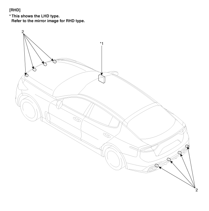
| 1. Integrated Body Control Module (IBU) | 2. Parking Sensor |
Description and Operation
System Configuration
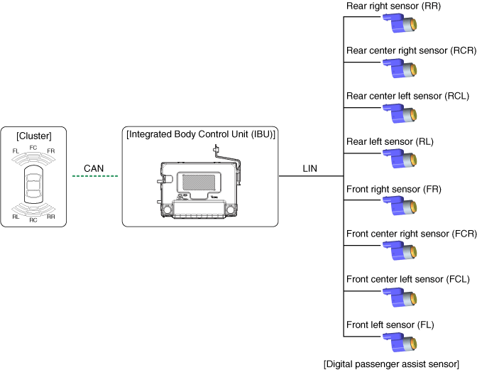
PDW consists of 8 sensors (4 front and 4 rear), which are used to detect obstacles and transmit the result on three separate warning levels: first, second and third to the IPM (IBU) via LIN communication. The IPM (IBU) determines the warning level based on the communication message transmitted from the slave sensors, then operates the buzzer or transmits data for display.
Block Diagram
System Operation Specification
Initial mode - Front sensor
System initialization time is 500 ms after the initial D gear IGN1+ input. Refer to 10 km/h.
The PDW recognizes the LID and sets the sensor ID during initialization.
PDW activates each sensor, then performs diagnosis after IPM (IBU) initialization is completed.
PDW starting buzzer operates normally when the sensor does not transmit an error message and after error diagnosis is completed.
If any failure is received from any sensor, the PDW starting buzzer does not operate, but the warning buzzer sounds momentarily.
If equipped with a display, a warning indicator is also displayed.
The buzzer sounds once when a sensor fails, but the display is shown continuously until the system is fully repaired.
The IPM (IBU) memorizes the completed initialization status of the front sensor until IGN 1 is turned off. It does not activate initialization when the next D gear input occurs.
In case of PDW SW OFF, system initialization is not activated.
If the PDW switch is turned on as shown below, it activates initialization.
PDW is deactivated when IGN1 is ON.
PDW activation when vehicle speed is below 10 km/h
Initialization is not related to the parking brake operation.
Initial mode - Rear sensor
The system initialization time is 500 ms after the initial R gear IGN1+.
The PDW recognizes the LID and sets the sensor ID during initialization.
PDW activates each sensor, then performs diagnosis after IPM (IBU) initialization is completed.
PDW starting buzzer operates normally when the sensor does not transmit an error message and after error diagnosis is completed.
If any failure is received from any sensor, the PDW starting buzzer does not operate, but the warning buzzer sounds momentarily.
If equipped with a display, a warning indicator is also displayed.
The buzzer sounds once when a sensor fails, but the display is shown continuously until the system is fully repaired.
The IPM (IBU) stores the completed rear sensor initialization status until IGN 1 is turned OFF. It does not activate initialization when the next R gear input is received.
Initialization is not related to the parking brake operation.
Normal mode - Front sensor
LIN communication starts and maintains the procedure after IGN1 ON + D gear input + speed below 10 km/h.
After initialization, the subroutine runs immediately without the PDW warning sound.
The obstacle warning consists of 3 levels: 1, 2, 3 steps. Level 1 and 2 warnings sound intermittently, and level 3 warning sounds continuously. Level 1 warning does not exist for the front ultrasonic sensor.
Type with display
Level 2 warning: Display operates without warning only.
Three-level warning: Warning + display
Type without display: Warning only
For the display, the data of each sensor is sent from the IPM (IBU) to the display, e.g. cluster. CAN communication is used for transmission, and the maximum gateway time is 50 ms.
Effective vehicle speed for RPDW operation is less than 10 km/h.
Does not operate when PDW SW is OFF.
Not related to parking brake operation.
Operation does not start or stops in N or P gear.
Normal mode - Rear sensor
LIN communication starts and maintains the procedure after IGN1 ON + R gear input.
The IBU sends a single request message to each sensor to check the initial system status and operate the four sensors in time. At this time, if there is no problem, the warning sounds after 500 ms with R gear shift and an interval of 300 ms.
After initialization, normal mode starts 100 ms after completion. Warning output.
The obstacle warning is divided into 3 levels.
The first and second levels sound intermittently, and the third warning sounds continuously.
For the display, the data of each sensor is sent from the IBU to the display, e.g. cluster.
CAN communication is used for transmission, and the maximum gateway time is 50 ms.
This is not related to vehicle speed.
When PDW SW is OFF, if the R gear signal is input, PDW SW changes to ON.
Not related to parking brake operation.
Operation does not start or stops in N or P gear.
Detection Area
Measurement conditions – PVC pole (diameter 75 mm, length 3 m), normal temperature
Distance to detected objects (measured directly in front of the sensor)
Front sensor
61 cm (24 in) - 100 cm (39.4 in): ± 15 cm (5.9 in)
31 cm (12.2 in) - 60 cm (23.6 in): ± 15 cm (5.9 in)
Less than 20 cm (7.9 in): ± 10 cm (3.9 in)
Rear sensor
61 cm (24.0 in) - 120 cm (47.2 in): ± 15 cm (5.9 in)
31 cm (12.2 in) - 60 cm (23.6 in): ± 15 cm (5.9 in)
Less than 30 cm (11.8 in): ± 10 cm (3.9 in)
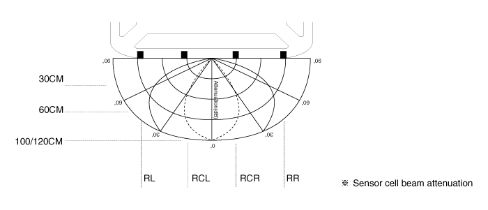
Horizontal Sensing Area
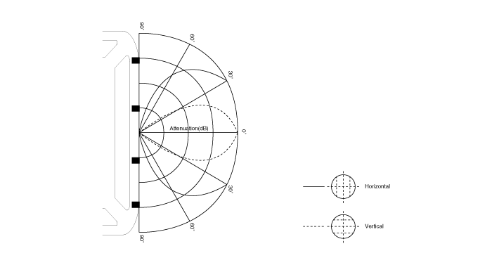
Vertical detection area
Distance measurement
Direct measurement
Transmission and reception are performed by one sensor
(FL, FCL, FCR, FR, RL, RCL, RCR, RR for each sensor configuration)
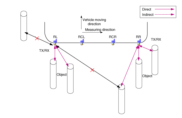
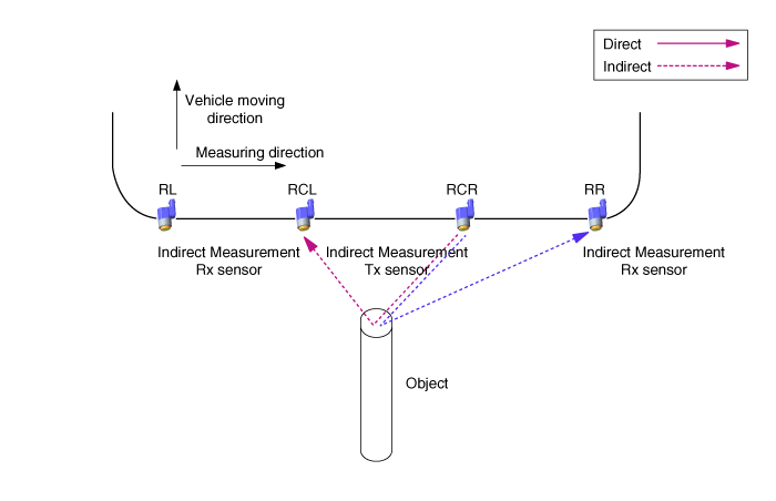
Indirect measurement
(FCL → FL, FCL → FCR, FCR → FCL, FCR → FR, RCL → RL, RCL → RCR, RCR → RCL, RCR → RR, performed in order)
With two or three sensors, one of them sends the transmission and the others receive the reception.
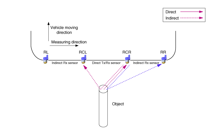
Direct and indirect measurement at one time
With two or three sensors, one sensor performs both transmission and reception, and the others perform reception only.
PDW-R warning system
When the PDW-R sensor detects an object, the warning is output through an audible warning device such as a buzzer. The PDW-R sensor sends data to the IBU via LIN communication, and the IBU outputs the audible warning for each PDW-R sensor by priority. It acts as a gateway only when it sends to a visual warning device such as the cluster.
Buzzer / display information processing in the IBU: For RL/RR sensor information, the IBU directly processes each sensor's information for display and buzzer functions. For buzzer output of CL/CR sensors, the IBU processes the center combination information by priority of both sensors. Otherwise, in case of display information failure, the IBU sends each sensor's information to the information cluster.
System operation specification - Front sensor
When the system is powered (after IGN ON and D gear), the MICOM checks each sensor channel. If no fault is detected, the buzzer sounds after 500 ms. However, if any fault is found, even in one sensor, the buzzer of the corresponding faulty sensor sounds instead of the initial start signal. If the PDW switch is in the OFF position, the system does not operate. The function to enter normal mode is shown below.
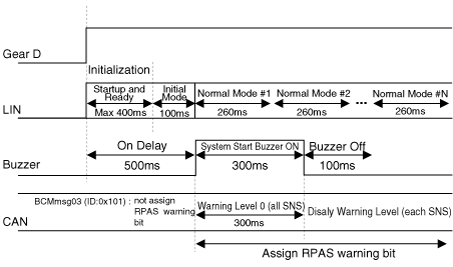
* In initial mode, the IPM (IBU) evaluates only sensor faults.
With D gear, the system operates as shown below.
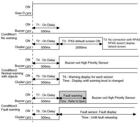
When D gear is released, the system operates as shown below.
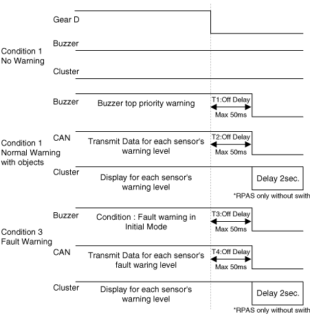
System Operation Specification - Rear Sensor
When the system is powered (after IGN ON and R gear), the MICOM checks each sensor channel. If no fault is detected, the buzzer sounds for 300 ms after 500 ms. However, if any fault is found, even in one sensor, the buzzer of the corresponding faulty sensor sounds instead of the initial start signal. The function to enter normal mode is shown below.
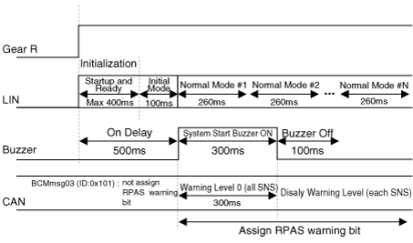
With R gear, the system function is as follows:
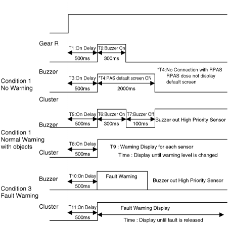
When the R gear is released, the system functions as shown below.
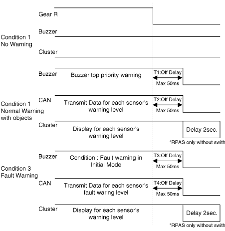
※ Permissible signal tolerance range ±10%
Warning Output Specification is classified by the distance between sensors
The state logic according to warning level priority is as follows. (identical sensors)
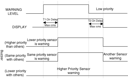
* Determination of α value
Low priority sensor off: α = 0 ms
Low priority sensor - 1st level warning: α < 340 ms
Low priority sensor - 2nd level warning: α < 170 ms
*Determination of β value
Low priority sensor - 1st level warning: β = 1700 ms
Low priority sensor - 2nd level warning: β = 1700 ms
Low priority sensor - 3rd level warning: β = 700 ms
Warning control by distance determination is as shown below.
First warning zone (front: 61 cm (24 in) - 100 cm (39.4 in), rear: 61 cm (24 in) - 120 cm (47.2 in))
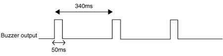
Second warning zone (front/rear: 31 cm (12.2 in) - 60 cm (23.6 in))
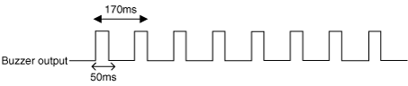
Third warning zone (front/rear: less than 30 cm (11.8 in))

Visual Warning Indicator Specification
Warning level by distance - front and rear sensors
When the transmission is in R, the cluster indicator illuminates as shown in the figure below. When the system detects an object, the indicator illuminates immediately. During object detection, if no object is present, the indicator illuminates with no alarm state for two seconds, and then turns off after the object is detected. (However, when the alarm changes from the third-stage alarm to the "No Alarm" state, the third-stage alarm indicator illuminates for two seconds and then turns off.)
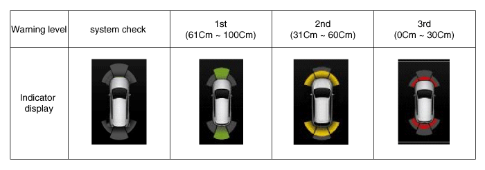
* It displays only the position of the detected obstacle.
* The indicator flashes once per second during the third-stage alarm.
* Built-in display (FCL/FCR, RCL/RCR).
Test yourself
A quick Kia Stinger CK quiz: every answer comes with an explanation and a link to the manual page.