Engine bottom side assembly
Assemble the engine bottom side in the reverse order of disassembly. Pay attention to the following points:
Note apply engine oil to each running and sliding part before reassembling.
Breather oil return plateWhen installing the breather oil return plate (1), apply thread lock to the bolts.
 : Thread lock cement
99000–32110 (thread lock cement super “1322” or equivalent)

Oil seal / bearing
Install the oil seal and bearings. Refer to “transmission installation” in section 5b .
Water jacket plug- Apply engine coolant to the o-rings of the water jacket plugs.
- Tighten each plug to the specified torque.
Caution replace the o-rings with new ones.
Tightening torque water jacket plug (a): 9,5 N·m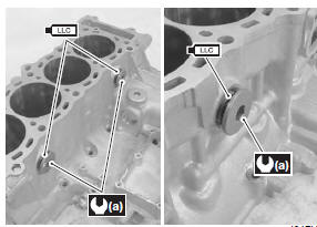
Oil gallery plug
Caution replace the gaskets with new ones.
- Apply thread lock to the oil gallery plug (m10) and tighten it to the specified torque.
: Thread lock cement 99000–32110 (thread lock cement super “1322” or equivalent) Tightening torque oil gallery plug (m10) (a): 18 N·m
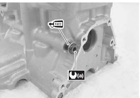
- Apply thread lock to the oil gallery plug (m12) and tighten it to the specified torque.
: Thread lock cement 99000–32110 (thread lock cement super “1322” or equivalent) Tightening torque oil gallery plug (m12) (b): 15 N·m
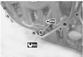
- Tighten the oil gallery plugs to the specified torque.
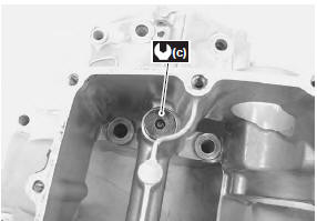

Oil jet
Install the oil jet (1) (for transmission).

Crankshaft journal bearing
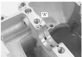
When fitting the crankshaft journal bearings to the upper and lower crankcases, be sure to fix the stopper part “a” first and press the other end.
Cautiondo not touch the bearing surfaces with your hands. Grasp by the edge of the bearing shell.
Noteinspect and select the crankshaft journal bearing if necessary. Refer to “crankshaft journal bearing inspection and selection” .
Piston and conrod
- Apply a small quantity of molybdenum oil solution onto each piston pin.
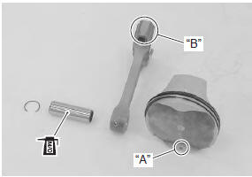
- Assemble the piston and conrod.
when installing the pistons, the indent “a” on the piston head must be brought to the other side of id code “b” on the conrod big end.
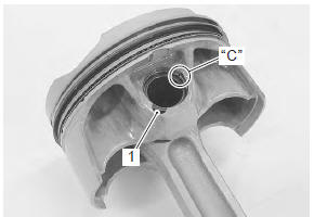
- Install the piston pin circlips (1).
use new piston pin circlips (1) to prevent circlip failure which will occur when it is bent.
Noteend gap of the circlip “c” should not be aligned with the cutaway in the piston pin bore.
- Apply a small quantity of molybdenum oil solution to the sliding surface of the pistons and cylinder walls.
be sure to install the pistons in the cylinders from which they were removed in disassembly, referring to the cylinder numbers, #1 through #4, scribed on the piston.
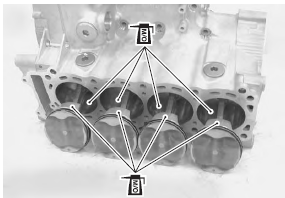
- Install the pistons with conrods into the cylinders from topside using the special tool.
when installing the pistons, the indent “d” of each piston head must be brought to the exhaust side.
Special tool (a): 09916–77310 (piston ring
compressor)

- Check that i.D. Code “e” on each conrod faces intake side.
Caution be sure to clean the conrod big end.
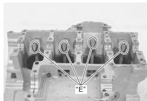
Piston cooling oil jet
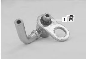
- Fit new o-ring (1) to each piston cooling oil jet and apply engine oil to it.
Caution use new o-ring to prevent oil pressure leakage.
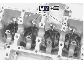
- Install each piston cooling oil jet.
apply a small quantity of thread lock to the bolts and tighten them to the specified torque.
 : Thread lock cement
99000–32110 (thread lock cement super “1322” or equivalent) Tightening torque piston cooling oil jet bolt (a): 10 N·m
Crankshaft
- Apply molybdenum oil to each crank pin bearing surface and crankshaft journal bearing surface.
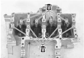
- Position the no. 2 And no. 3 Conrod big ends on the same side, and the no. 1 And no. 4 Conrod big ends on the opposite side of no. 2 And no. 3.

- Set the crankshaft onto the conrods and upper crankcase.
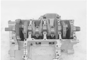
- Apply molybdenum oil to each crank pin and bearing surface.
Caution be sure to clean the conrod big end.
M/o: molybdenum oil (molybdenum oil solution)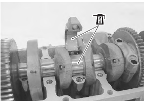
- When fitting the conrod cap, make sure that I.D.
Code “a” on each conrod faces intake side.
- Apply engine oil to the conrod cap bolts.
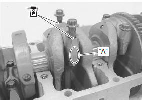
- Tighten the conrod cap bolt by using a 10 mm, 12 point socket wrench in the following two steps.
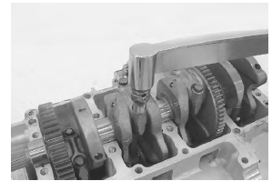
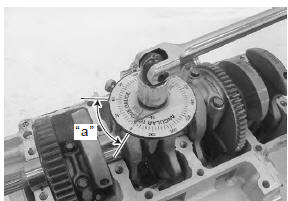
60°
- Apply engine oil to the conrod big end side surfaces.
- Apply molybdenum oil to each crankshaft journal and bearing lightly.
- Check the conrod movement for smooth turning.
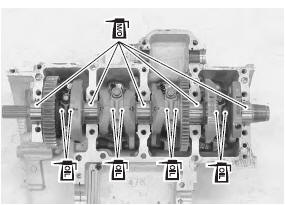
- Insert the right and left thrust bearings with the oil grooves “b” facing towards the crankshaft web.
- right-thrust bearing has green painting.
- Inspect and select the crankshaft thrust clearance if necessary. Refer to “crankshaft thrust clearance inspection and selection” .

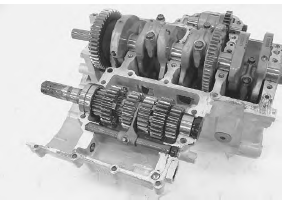
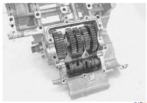
Transmission
Install the transmission. Refer to “transmission installation” in section 5b .
Balancer shaft
- Apply a molybdenum oil solution to each balancer shaft journal and bearing lightly.
- Set the balancer shaft so that its punch mark “a” is aligned with the index “b” on the crankshaft.
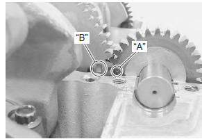
- Install the plug (1).
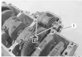
Crankcase
- Install the dowel pins and o-rings (1).
Caution replace the o-rings with new ones.

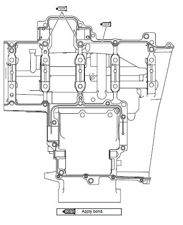
- Apply bond to the mating surface of the lower crankcase as follows.
- make mating surfaces free from moisture, oil, dust and other foreign materials.
- Spread the sealant on surfaces thinly to form an even layer, and assemble the crankcases within a few minutes.
- Take extreme care not to apply sealant to any oil hole, oil groove and bearing.
- Apply sealant to distorted surfaces as it forms a comparatively thick film.
 : Sealant 99000–31140 (suzuki
bond no.1207B or equivalent)
- Tighten the crankshaft journal bolts (m9). Tighten each bolt a little at a time to equalize the pressure in the following two steps.
Caution fit new gasket washers to the bolts “a” to prevent oil leakage.
Tightening torque crankshaft journal bolt (m9): 18 N·m then turn in 50°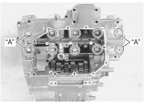
- Tighten the crankcase bolts a little at a time to equalize the pressure.
- Install the cap (2).
- fit new gasket washers to the bolts “b” to prevent oil leakage.
- Fit new o-ring to the cap (2) and apply grease to it.
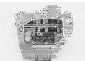
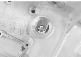

- After the crankshaft journal bolts and crankcase bolts have been tightened, check that the crankshaft rotates smoothly.
- Also check that the driveshaft and countershaft rotate smoothly.
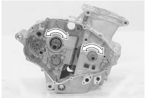
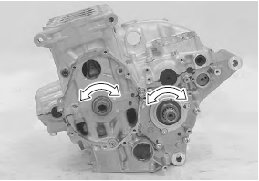
- Install the clutch push rod oil seal retainer (3).
- Apply thread lock to the bolts.
 : Thread lock cement
99000–32110 (thread lock cement super “1322” or equivalent)

Oil pump
- Install the breather oil return pipe (1).
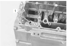
- Apply grease to new o-ring (2).
 : Grease 99000–25010 (suzuki
super grease “a” or equivalent)
Caution use a new o-ring to prevent oil leakage.
- Install the o-ring and dowel pins.
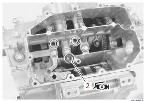
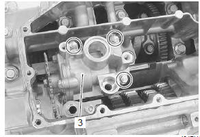
- Install the oil pump (3) and tighten the oil pump bolts to the specified torque.
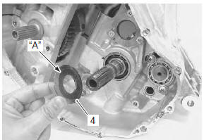
- Install the thrust washer (4) to the countershaft.
Note the chamfer side “a” of thrust washer should face the crankcase side.
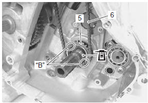
- Install the oil pump drive sprocket (5) to the countershaft.
Note teeth “b” on the sprocket must face the clutch side.
- Pass the chain (6) between the oil pump drive and driven sprockets.
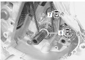
- Apply engine oil to the countershaft
- Apply engine oil to the bearing (7) and spacer (8) and install them into the sprocket.
Oil strainer / oil pressure regulator
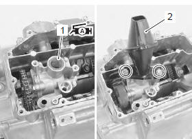
- Apply grease to new o-ring (1).
Caution use a new o-ring to prevent oil leakage.
 : Grease 99000–25010 (suzuki
super grease “a” or equivalent)
- Install the oil strainer (2).
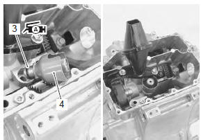
- Apply grease to new o-ring (3).
Caution use a new o-ring to prevent oil leakage.
 : Grease 99000–25010 (suzuki
super grease “a” or equivalent)
- Push in the oil pressure regulator (4) to the oil pump as shown.
Oil pan
- Install new gasket.
Caution use new gasket to prevent oil leakage.
- Install the oil pan (1) and plate (2).
- Apply thread lock to the plate bolts “a”.
 : Thread lock cement
99000–32110 (thread lock cement super “1322” or equivalent)
- Tighten the oil pan bolts and plate bolts diagonally to the specified torque.
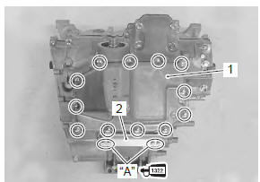
Oil filter
Install the oil filter with the special tool. Refer to “engine oil and filter replacement” in section 0b .
Special tool (a): 09915–40610 (oil filter wrench)

Oil pressure switch
- Apply bond to the thread part of oil pressure switch and tighten oil pressure switch to the specified torque.
Note be careful not to apply bond to the hole of thread end.
 : Sealant 99000–31140 (suzuki
bond no.1207B or equivalent) Tightening torque oil pressure switch: 14 N·m
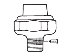
- Route the oil pressure switch lead wire properly and tighten the screw to the specified torque. Refer to “wiring harness routing diagram” in section 9a .
- Apply grease to the o-ring.
Caution replace the o-ring with a new one.
Note insert the gear position switch pin “a” into the gearshift cam hole “b”.
 : Grease 99000–25010 (suzuki
super grease “a” or equivalent)
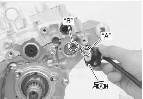
- Tighten the gear position switch mounting bolts to the specified torque.

Water pump
- Apply grease to new o-ring (1).
Caution use the new o-ring to prevent oil leakage.
 : Grease 99000–25010 (suzuki
super grease “a” or equivalent)
- Install the water pump assembly with the slot of the pump shaft end “a” securely engaged with the flat “b” of the oil pump shaft.

- Tighten the water pump mounting bolts (2) to the specified torque.
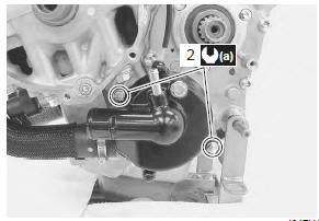
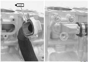
- Apply engine coolant to the o-ring.
Caution replace the o-ring with a new one.
- Tighten the water inlet connector mounting bolts.
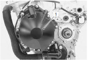
Generator
Install the generator rotor and cover (1). Refer to “generator removal and installation” in section 1j .
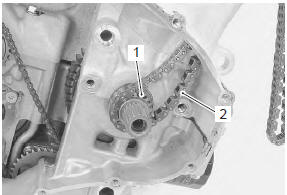
Cam chain / cam chain tensioner / cam chain guide no. 1
- Install the cam chain drive sprocket (1) to the crankshaft.
when installing the cam chain drive sprocket, align the wide spline teeth of the sprocket and crankshaft.
- Install the cam chain (2).
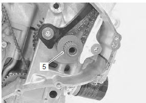
- Insert the cam chain tensioner and tighten the cam chain tensioner bolt (3) to the specified torque.
- Insert the cam chain guide no. 1 While pulling the chain upward.
- Tighten the cam chain guide no. 1 Bolt (4) to the specified torque.

- Install the washer (5).
Starter clutch / starter torque limiter
Install the starter clutch (1) and starter torque limiter (2) component parts. Refer to “starter clutch removal and installation” in section 1i and “starter torque limiter removal and installation” in section 1i .
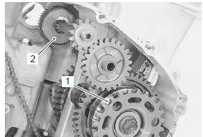
Gearshift system
Install the gearshift cam plate (1) and gearshift shaft (2).
Refer to “gearshift shaft / gearshift cam plate removal and installation” in section 5b .
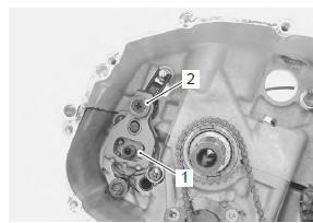
Clutch
Install the clutch component parts (1). Refer to “clutch installation” in section 5c .
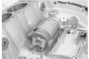
Starter motor
Install the starter motor (1). Refer to “starter motor removal and installation” in section 1i .
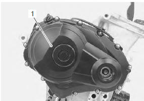
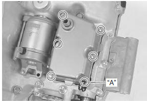
Crankcase breather (pcv) cover
- Apply bond to the hatching part of crankcase breather (pcv) cover.
 : Sealant 99000–31140 (suzuki
bond no.1207B or equivalent)

- Fit the clamp to the bolt “a”. Refer to “wiring harness routing diagram” in section 9a .
- Tighten the crankcase breather (pcv) cover bolts.
Engine top side
Assemble the engine top side. Refer to “engine top side disassembly” .
Test yourself
A quick Suzuki GSX-R 1000 quiz: every answer comes with an explanation and a link to the manual page.