ECU Terminals
ECU TERMINALS
AIR CONDITIONING AMPLIFIER ASSEMBLY
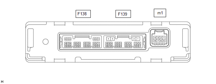
HINT:
Check the rear of the connector while it is connected to the air conditioning amplifier assembly.
Terminal No. (Symbol) | Wire Color | Terminal Description | Condition | Specified Condition |
|---|---|---|---|---|
F138-1 (SG-1) - Body Ground |
LG - Body ground |
Ground for Cooler Thermistor (Room Temperature Sensor) |
Always |
Below 1 V |
F138-2 (SG-2) - Body Ground |
G - Body ground |
Ground for Air Conditioning Pressure Sensor |
Always |
Below 1 V |
F138-6 (S5-3) - F138-2 (SG-2) |
GR - G |
Power Source for Air Conditioning Pressure Sensor |
Ignition Switch in ON position |
4,75 à 5,25 V |
Ignition Switch in OFF position |
Below 1 V |
|||
F138-14 (TR) - F138-1 (SG-1) |
B - LG |
Cooler Thermistor (Room Temperature Sensor) Signal |
|
1,8 à 2,2 V |
|
1,2 à 1,6 V |
|||
F138-24 (PRE) - F138-2 (SG-2) |
V - G |
Air Conditioning Pressure Sensor Signal |
|
4.61 V Minimum |
|
Below 0.74 V |
|||
|
0,74 à 4,61 V |
|||
F139-1 (B) - F139-4 (GND) |
V - W-B |
Power Source (Backup) |
Always |
11 à 14 V |
F139-2 (IG+) - F139-4 (GND) |
B - W-B |
Power supply (IG) |
Ignition Switch in ON position |
11 à 14 V |
Ignition Switch in OFF position |
Below 1 V |
|||
F139-3 (SOL+) - F139-4 (GND) |
B - W-B |
Compressor Solenoid Operation Signal |
|
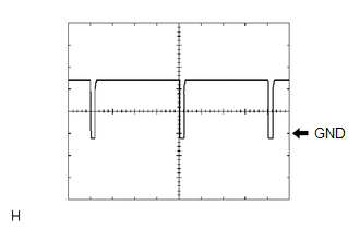
Pulse generation (See waveform 1) |
F139-4 (GND) - Body ground |
W-B - Body ground |
Ground for Main Power Supply |
Always |
Below 1 V |
F139-6 (BLW) - F139-4 (GND) |
Y - W-B |
Blower Motor Speed Control Signal |
|
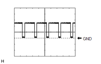
Pulse generation (see waveform 2) |
F139-11 (CANH) - F139-12 (CANL) |
P - SB |
CAN communication signal |
CAN Communication is Performed |
Pulse generation |
F139-14 (LIN1) - F139-4 (GND) |
BE - W-B |
LIN Communication Signal (Air Conditioning Control Assembly) |
Ignition Switch in ON position |
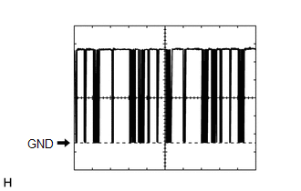
Pulse generation (See waveform 3) |
m1-2 (BUSG) - Body Ground |
B - Body ground |
Ground for BUS IC |
Always |
Below 1 V |
m1-3 (BUS) - m1-2 (BUSG) |
L - B |
BUS IC Control Signal |
Ignition Switch in ON position |
Pulse generation (see waveform 4) |
m1-4 (BUSB) - m1-2 (BUSG) |
R - B |
Power Source for BUS IC |
Always |
11 à 14 V |
m1-5 (SG-4) - Body Ground |
GR - Body ground |
Ground for No. 1 Cooler Thermistor (Evaporator Temperature Sensor) |
Always |
Below 1 V |
m1-6 (TE) - m1-5 (SG-4) |
GR - GR |
No. 1 Cooler Thermistor (Evaporator Temperature Sensor) |
|
1,7 à 2,1 V |
|
0,9 à 1,3 V |
(a) Waveform 1:
Item | Content |
|---|---|
Terminal No. (Symbol) |
F139-3 (SOL+) - F139-4 (GND) |
Oscilloscope Setting |
5 V/DIV., 500 µs/DIV. |
Vehicle Operating Conditions |
|
(b) Waveform 2:
Item | Content |
|---|---|
Terminal No. |
F139-6 (BLW) - F139-4 (GND) |
Oscilloscope Setting |
2 V/DIV., 1 ms/DIV. |
Vehicle Operating Conditions |
|
(c) Waveform 3:
Item | Content |
|---|---|
Terminal No. |
F139-14 (LIN1) - F139-4 (GND) |
Oscilloscope Setting |
2 V/DIV., 20 ms/DIV. |
Vehicle Operating Conditions |
Ignition Switch in ON position |
(d) Waveform 4:
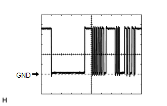
Item | Content |
|---|---|
Terminal No. |
m1-3 (BUS) - m1-2 (BUSG) |
Oscilloscope Setting |
2 V/DIV., 2 ms/DIV. |
Vehicle Operating Conditions |
Ignition Switch in ON position |
AIR CONDITIONING CONTROL ASSEMBLY
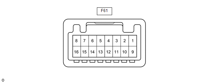
HINT:
Check the rear of the connector while it is connected to the air conditioning control assembly.
Terminal No. (Symbol) | Wire Color | Terminal Description | Condition | Specified Condition |
|---|---|---|---|---|
F61-16 (GND) - Body Ground |
W-B - Body ground |
Ground for Air Conditioning Control Assembly |
Always |
Below 1 V |
F61-2 (LIN1) - Body Ground |
BE - Body ground |
LIN Communication Signal |
Ignition Switch in ON position |
Pulse generation (See waveform 1) |
F61-10 (IG+) - F61-16 (GND) |
BE - W-B |
Power supply (IG) |
Ignition Switch in OFF position |
Below 1 V |
Ignition Switch in ON position |
11 à 14 V |
(a) Waveform 1:
Item | Content |
|---|---|
Terminal No. |
F61-2 (LIN1) - Body Ground |
Oscilloscope Setting |
2 V/DIV., 20 ms/DIV. |
Vehicle Operating Conditions |
Ignition Switch in ON position |