Lost Communication with Front Panel LIN (B14B2)
DESCRIPTION
The air conditioning control assembly communicates with the air conditioner amplifier assembly via LIN communication.
If the LIN communication system malfunctions, the air conditioner amplifier assembly does not operate even if the air conditioning control assembly is operated.
DTC No. | Detection Item | DTC Detection Condition | Suspected Area | Memory |
|---|---|---|---|---|
B14B2 |
Communication Lost with LIN Front Panel |
Communication Lost with A/C Control Assembly |
|
Stored (10 seconds minimum)* |
- *: The A/C amplifier assembly stores this DTC if the malfunction occurs within the time period shown in parentheses.
WIRING DIAGRAM
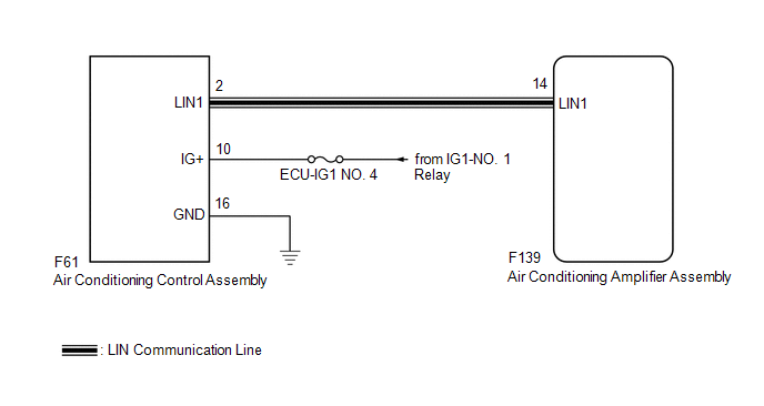
PRECAUTION / NOTICE / HINT
NOTICE:
Check the fuses for the circuits related to this system before performing the following procedure.
PROCEDURE
CHECK HARNESS AND CONNECTOR (AIR CONDITIONING CONTROL ASSEMBLY - IG POWER SOURCE)
(a) Disconnect the air conditioning control assembly connector. |
|
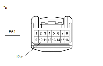
(b) Measure the voltage according to the value(s) in the table below.
Standard voltage:
Tester Connection | Ignition switch position | Specified Condition |
|---|---|---|
F61-10 (IG+) - Body ground |
Ignition Switch in ON position |
11 à 14 V |
F61-10 (IG+) - Body ground |
Ignition Switch in OFF position |
Below 1 V |
| NG |  |
REPAIR OR REPLACE HARNESS OR CONNECTOR |
|

CHECK HARNESS AND CONNECTOR (AIR CONDITIONING CONTROL ASSEMBLY - BODY GROUND)
(a) Measure the resistance according to the value(s) in the table below.
Standard resistance:
Tester Connection | Condition | Specified Condition |
|---|---|---|
F61-16 (GND) - Body Ground |
Always |
Below 1 Ω |
| NG | |
REPAIR OR REPLACE HARNESS OR CONNECTOR |
|
CHECK HARNESS AND CONNECTOR (AIR CONDITIONER AMPLIFIER ASSEMBLY - AIR CONDITIONING CONTROL ASSEMBLY)
(a) Disconnect the F139 connector from the air conditioning amplifier assembly.
(b) Measure the resistance according to the value(s) in the table below.
Standard resistance:
Tester Connection | Condition | Specified Condition |
|---|---|---|
F61-2 (LIN1) - F139-14 (LIN1) |
Always |
Below 1 Ω |
F61-2 (LIN1) or F139-14 (LIN1) - Body ground |
Always |
10 kΩ minimum |
| NG | |
REPAIR OR REPLACE HARNESS OR CONNECTOR |
|
CHECK AIR CONDITIONING AMPLIFIER ASSY
(a) Reconnect the air conditioner amplifier assembly connector.
(b) Turn the ignition switch to ON.
(c) Connect an oscilloscope to terminals F139-14 (LIN1) and F139-4 (GND) of the air conditioner amplifier assembly and check the waveform. OK: The waveform is the same as that shown in the diagram.
|
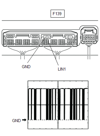 |
| NG | |
REPLACE AIR CONDITIONING AMPLIFIER ASSEMBLY |
|
CHECK AIR CONDITIONING CONTROL ASSY
(a) Reconnect the air conditioning control assembly connector. |
|
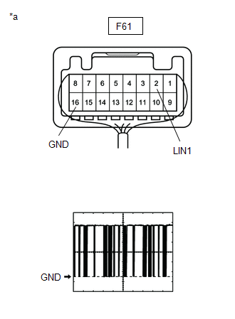
(b) Turn the ignition switch to ON.
(c) Connect an oscilloscope to terminals F61-2 (LIN1) and F61-16 (GND) of the air conditioning control assembly and check the waveform.
OK:
The waveform is the same as that shown in the diagram.
Item | Content |
|---|---|
Oscilloscope Setting |
2 V/DIV., 20 ms/DIV. |
Vehicle Operating Conditions |
Ignition Switch in ON position |
| OK | |
REPLACE AIR CONDITIONING AMPLIFIER ASSEMBLY |
| NG | |
REPLACE AIR CONDITIONING CONTROL ASSEMBLY |