Ambient Temperature Display System
DESCRIPTION
The thermistor assembly is installed at the front of the condenser radiator assembly to detect the ambient temperature used to control AUTO mode of the air conditioning system. The sensor is connected to the air conditioning amplifier assembly and detects changes in ambient temperature. This data is used to control the cabin temperature. The sensor sends a signal to the air conditioning amplifier assembly. The resistance of the thermistor assembly changes according to the ambient temperature.
The resistance increases as the temperature decreases. Conversely, the resistance decreases as the temperature increases. The air conditioning amplifier assembly applies a voltage (5 V) to the thermistor assembly and detects voltage changes caused by changes in the resistance of the thermistor assembly.
NOTICE:
The thermistor assembly is installed at the front of the condenser radiator assembly in the engine compartment and detects the temperature around its installation location (the detected ambient temperature is the temperature around the thermistor assembly, not the outside air temperature around the vehicle). Therefore, the temperature around the thermistor assembly changes depending on heat radiated from the engine compartment, and the displayed ambient temperature is affected by vehicle speed. In the following cases, the outside air temperature around the vehicle and the displayed value differ, and the update speed of the displayed value is delayed. However, this is not a malfunction.
- When the vehicle is stopped or driven at low speed, the value is not updated to a higher temperature, in order to minimize the effect of engine heat on AUTO heating and air conditioning control. The same applies when driving at medium to high speed, so updating to a higher temperature is delayed. However, the value is updated to a lower temperature regardless of vehicle speed.
- The ambient temperature around the thermistor assembly installation area changes significantly for a reason other than heat radiated from the engine (vehicle garage, entering or exiting a tunnel, etc.).
WIRING DIAGRAM
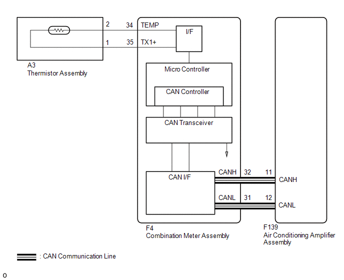
PRECAUTION / NOTICE / HINT
NOTICE:
- After turning the ignition switch OFF, a waiting time may be required before disconnecting the cable from the negative (-) battery terminal. Therefore, be sure to read the precautions for disconnecting the cable from the negative (-) battery terminal before performing the work.
Click here

- Before starting the inspection, dissipate residual heat from the engine compartment (engine unit and coolant hoses, etc.) after stopping the engine (when the vehicle is parked after being driven). Move and park the vehicle in one of the following temperature measurement locations.
- A location in the workshop where ambient temperature variations in the area around the vehicle are relatively low.
- A location with a flat surface made of a material such as concrete, which transmits a relatively low amount of heat from the floor.
- A location free from thermal influence around the vehicle being inspected, such as other vehicles with running engines or motors, exhaust gas lines routed along exhaust pipes, heaters, etc.
- Ignition switch operation during vehicle inspection while parked:
Turn the ignition switch to ON. (Do not start the engine.)
PROCEDURE
CHECK WHETHER DTCs ARE OUTPUT
(a) Clear the DTCs.
Click here
(b) Check the DTCs when the following conditions are met.
Click here
NOTICE:
During inspection with the vehicle parked, perform the inspection with the ignition switch in the ON position (do not start the engine).
Result:
Result | Proceed to |
|---|---|
DTC B1412 is not output |
A |
DTC B1412 is output |
B |
| B |  |
GO TO DTC B1412 |
|

INSPECT THERMISTOR ASSEMBLY
(a) Remove the thermistor assembly.
Click here
(b) Inspect the thermistor assembly.
Click here
| NG | |
REPLACE THERMISTOR ASSEMBLY |
|
INSPECT WIRE HARNESS AND CONNECTOR (THERMISTOR ASSEMBLY - COMBINATION METER ASSEMBLY)
NOTICE:
During inspection with the vehicle parked, perform the inspection with the ignition switch in the OFF position (do not start the engine).
(a) Disconnect connector A3 from the thermistor assembly.
(b) Disconnect the combination meter assembly connector F4.
(c) Measure the resistance according to the value(s) in the table below.
Standard resistance:
Tester Connection | Condition | Specified Condition |
|---|---|---|
A3-2 - F4-34 (TEMP) |
Always |
Below 1 Ω |
A3-1 - F4-35 (TX1+) |
Always |
Below 1 Ω |
A3-1 - A3-2 |
Always |
10 kΩ minimum |
A3-2 or F4-34 (TEMP) - Body Ground |
Always |
10 kΩ minimum |
A3-1 or F4-35 (TX1+) - Body Ground |
Always |
10 kΩ minimum |
| NG | |
REPAIR OR REPLACE HARNESS OR CONNECTOR |
|
CHECK AMBIENT TEMPERATURE COMPARISON
(a) Disconnect the cable from the negative (-) battery terminal.
NOTICE:
Make sure that the wire harness(es) and connector(s) of the vehicle being inspected are connected. Once the ignition switch is turned OFF, the navigation system retains memory and various settings for approximately 6 minutes. Therefore, be sure to disconnect the cable from the negative (-) battery terminal only after at least 6 minutes have elapsed since the ignition switch was turned OFF.
(b) Disconnect the cable from the negative (-) battery terminal and wait at least 90 seconds.
HINT:
The air conditioning amplifier assembly stores the thermistor assembly detection value for 1 hour after the ignition switch is turned OFF. Therefore, it is necessary to turn off the power supply to the air conditioning amplifier assembly and erase the stored values after the ignition switch has been turned OFF.
(c) Connect the cable to the negative (-) battery terminal.
(d) Using a thermometer, measure the ambient temperature around the thermistor assembly installation area and record this value.
NOTICE:
- During inspection with the vehicle parked, perform the inspection with the ignition switch in the ON position (do not start the engine).
- Position the thermometer so that the measuring tip is at approximately the same height and lateral position as the thermistor assembly installed behind the front grille and approximately 5 cm from the front grille surface, then hold the thermometer in this position.
- After turning the ignition switch ON, the ambient temperature, the detected signal value, and the temperature of the sensing part of the thermistor assembly and the measuring tip of the thermometer equalize. Therefore, be sure to wait approximately 6 minutes before measuring.
- If the temperature-sensing part of the thermistor assembly is touched, the body temperature of the technician may cause an inaccurate temperature reading. For this reason, be sure not to touch the temperature sensor when measuring the ambient temperature of the installation area around the thermistor assembly.
- Do not move the thermometer from the held position, touch the measuring tip, or allow it to contact the front grille.
(e) Record the ambient temperature value displayed on the multi-information display of the combination meter assembly.
(f) Compare the ambient temperature of the installation area around the thermistor assembly with the ambient temperature value displayed on the multi-information display of the combination meter assembly.
Standard:
The ambient temperature of the installation area around the thermistor assembly is approximately the same as the ambient temperature value displayed on the multi-information display of the combination meter assembly.
| OK | |
END |
| NG | |
REPLACE AIR CONDITIONING AMPLIFIER ASSEMBLY |