Communication Malfunction (Ic Bus) (B1497)
DESCRIPTION
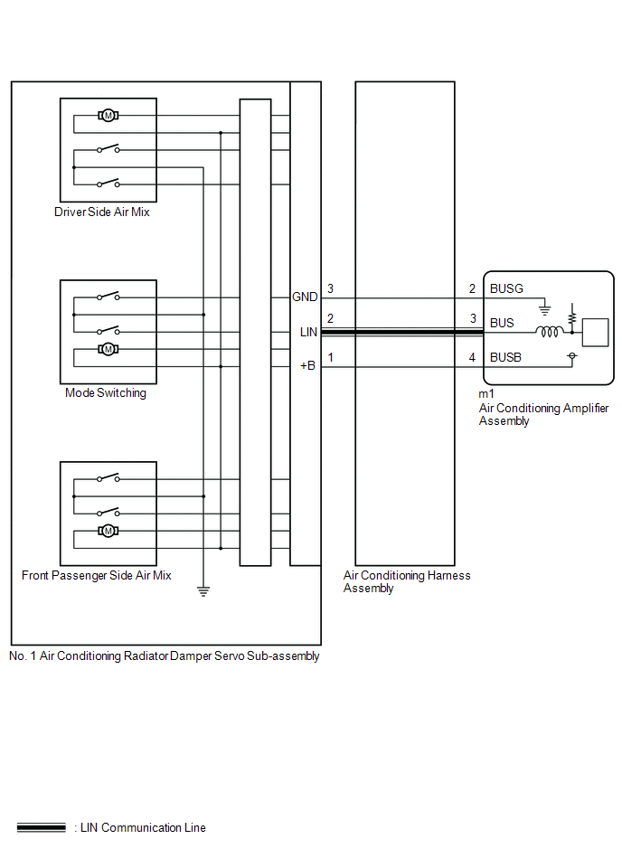
The air conditioning harness assembly connects the air conditioner amplifier assembly and the actuators. The air conditioner amplifier assembly supplies power and sends operation commands to each actuator through the air conditioning harness assembly. Each actuator sends door position information to the air conditioner amplifier assembly.
DTC No. | Detection Item | DTC Detection Condition | Suspected Area | Memory |
|---|---|---|---|---|
B1497 |
Communication Malfunction (IC Bus) |
One of the following conditions is met
|
|
Stored (10 seconds minimum)* |
- *: The A/C amplifier assembly stores this DTC if the malfunction occurs within the time period shown in parentheses.
Vehicle Operating Conditions |
|||
|---|---|---|---|
Sequence 1 | Sequence 2 |
||
Diagnostic Condition |
Ignition Switch in ON position |
○ |
○ |
Malfunction Status |
Communication Line Malfunction |
○ |
- |
Open in Communication Line |
- |
○ |
|
Detection Duration |
10 seconds minimum |
10 seconds minimum |
|
Number of Trips |
1 trip(s) |
1 trip(s) |
|
HINT:
The DTC is output when the conditions for any one of the sequences in the table above are met.
WIRING DIAGRAM
PROCEDURE
PERFORM ACTIVE TEST USING TECHSTREAM
(a) Connect the Techstream to the DLC3.
(b) Turn the ignition switch to ON.
(c) Turn on the Techstream.
(d) Select the following menu items: Body Electrical / Air Conditioner / Active Test.
(e) Perform the Active Test by following the Techstream instructions.
Body Electrical > Air Conditioner > Active TestTester display | Item | Control Range | Diagnostic Note |
|---|---|---|---|
Air Mix Servo Targ Pulse(D) |
Pulse of A/C Radiator Damper Servo Sub-assembly No. 1 (Driver Side Air Mix) |
Min.: 128 Max.: 383 |
Operates between 255 and 347 pulses |
Air Mix Servo Targ Pulse(D)
OK:
The No. 1 air conditioning radiator air door servo motor operates normally.
Result:
Result | Proceed to |
|---|---|
The No. 1 air conditioning radiator air door servo motors malfunction. |
A |
The No. 1 air conditioning radiator air door servo motors operate normally. |
B |
| B |  |
GO TO STEP 4 |
|

CHECK AIR CONDITIONING HARNESS ASSEMBLY (AIR CONDITIONER AMPLIFIER ASSEMBLY - NO. 1 AIR CONDITIONING RADIATOR AIR DOOR SERVO SUB-ASSEMBLY)
NOTICE:
When checking the air conditioner amplifier assembly, do not place the tester probes too close together to prevent short circuits.
(a) Disconnect the m1 connector from the air conditioner amplifier assembly.
(b) Disconnect the connector from the No. 1 air conditioning radiator air door servo sub-assembly.
(c) Measure the resistance according to the value(s) in the table below.
Standard resistance:
Tester Connection | Condition | Specified Condition |
|---|---|---|
m1-2 (BUS G) - Body ground |
Always |
Below 1 Ω |
m1-3 (BUS) - 2 (LIN) |
Always |
Below 1 Ω |
m1-4 (BUSB) - 1 (+B) |
Always |
Below 1 Ω |
| NG | |
REPLACE AIR CONDITIONING HARNESS ASSEMBLY |
|
CHECK AIR CONDITIONING AMPLIFIER ASSY
NOTICE:
When checking the air conditioner amplifier assembly, do not place the tester probes too close together to prevent short circuits.
(a) Turn the ignition switch to ON.
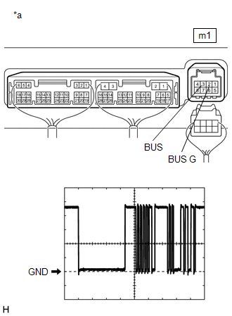
(b) Connect an oscilloscope to terminals m1-2 (BUS G) and m1-3 (BUS) of the air conditioner amplifier assembly and check the waveform. OK: The waveform is the same as that shown in the diagram. HINT: The waveform varies depending on the blower speed.
|
|
| OK | |
REINSTALL AIR CONDITIONING RADIATOR DAMPER SERVO SUB-ASSEMBLY NO. 1 |
| NG | |
REPLACE AIR CONDITIONING AMPLIFIER ASSEMBLY |
CHECK DTCs*
(a) Clear the DTCs.
Click here
(b) Check DTCs.
Click here
Result:
Result | Proceed to |
|---|---|
No DTCs are output |
A |
DTCs are output |
B |
| A | |
USE SIMULATION METHOD TO CHECK |
| B | |
REPLACE AIR CONDITIONING AMPLIFIER ASSEMBLY |