Antenna Coil Open / Short Circuit (B2784)
DESCRIPTION
If an open or short circuit is detected in the antenna coil built into the transponder key coil, the transponder key ECU assembly records this DTC.
DTC No. | Detection Item | DTC Detection Condition | Suspected Area | Note |
|---|---|---|---|---|
B2784 |
Antenna coil open / short circuit |
One of the following conditions is met
|
|
|
- *1: Only output when a malfunction is detected.
Vehicle Operating Conditions |
|||
|---|---|---|---|
Sequence 1 | Sequence 2 |
||
Diagnostic Condition |
Always |
○ |
○ |
Malfunction Status |
The antenna coil in the transponder key coil has an open circuit. |
○ |
- |
The antenna coil in the transponder key coil has a short circuit. |
- |
○ |
|
Detection Duration |
- |
- |
|
Number of Trips |
1 trip(s) |
1 trip(s) |
|
HINT:
The DTC is output when the conditions for any one of the sequences in the table above are met.
Vehicle condition and fail-safe function when a malfunction is detectedVehicle Condition When Malfunction Is Detected | Fail-safe function when a malfunction is detected |
|---|---|
The engine does not start. |
- |
DTC No. | Data List and Active Test |
|---|---|
B2784 |
Antenna Coil Status |
WIRING DIAGRAM
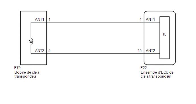
PRECAUTION / NOTICE / HINT
NOTICE:
- If the transponder key ECU assembly is replaced, refer to the registration section.
Click here

- After repair, make sure no DTCs are output by performing the "DTC Output Confirmation Operation" procedure.
PROCEDURE
CLEAR DTCs
(a) Clear the DTCs.
Body Electrical > Immobiliser > Clear DTCs
|

CHECK WHETHER DTCs ARE OUTPUT
(a) Check the DTCs.
Body Electrical > Immobiliser > Trouble CodesHINT:
Before checking the DTCs, perform the "DTC Output Confirmation Operation" procedure.
OK:
DTC B2784 is not output.
Result:
Result | Proceed to |
|---|---|
DTC B2784 is not output |
A |
DTC B2784 is output |
B |
| A |  |
USE SIMULATION METHOD TO CHECK |
|
CHECK CONNECTOR CONNECTION
(a) Make sure the connectors are properly connected to the transponder key coil.
|
CLEAR DTCs
(a) Clear the DTCs.
Body Electrical > Immobiliser > Clear DTCs
|
CHECK WHETHER DTCs ARE OUTPUT
(a) Check the DTCs.
Body Electrical > Immobiliser > Trouble CodesHINT:
Before checking the DTCs, perform the "DTC Output Confirmation Operation" procedure.
OK:
DTC B2784 is not output.
Result:
Result | Proceed to |
|---|---|
DTC B2784 is not output |
A |
DTC B2784 is output |
B |
| A | |
END (CONNECTOR WAS NOT PROPERLY CONNECTED) |
|
INSPECT TRANSPONDER KEY COIL (OUTPUT)
(a) Check the waveform using an oscilloscope.
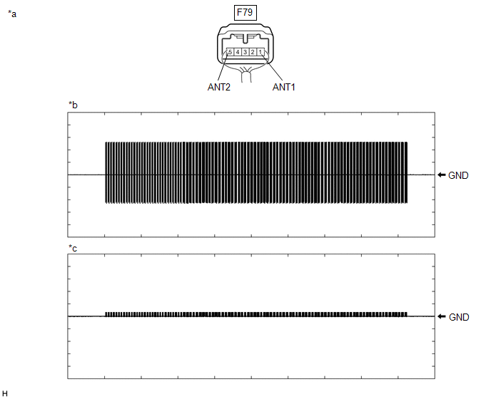
*a |
Component with Wire Harness Connected (Transponder Key Coil) |
*b |
Waveform 1 |
*c |
Waveform 2 |
- |
- |
Item | Content |
|---|---|
Tester Connection |
F79-1 (ANT1) ←→ Body ground |
Oscilloscope Setting |
20 V/DIV., 2 s/DIV. |
Condition |
Within 3 seconds after inserting the key into the ignition key cylinder |
Item | Content |
|---|---|
Tester Connection |
F79-5 (ANT2) ←→ Body ground |
Oscilloscope Setting |
20 V/DIV., 2 s/DIV. |
Oscilloscope Setting |
Within 3 seconds after inserting the key into the ignition key cylinder |
OK:
The waveform is the same as shown in the diagram
| OK | |
REPLACE TRANSPONDER KEY COIL |
|
INSPECT WIRE HARNESS AND CONNECTOR (TRANSPONDER KEY ECU ASSEMBLY - TRANSPONDER KEY COIL AND BODY GROUND)
(a) Disconnect connector F22 from the transponder key ECU assembly.
(b) Disconnect the F79 connector from the transponder key coil connector.
(c) Measure the resistance according to the value(s) in the table below.
Standard resistance:
Tester Connection | Condition | Specified Condition |
|---|---|---|
F22-4 (ANT1) - F79-1 (ANT1) |
Always |
Below 1 Ω |
F22-15 (ANT2) - F79-5 (ANT2) |
Always |
Below 1 Ω |
F22-4 (ANT1) - Body ground |
Always |
10 kΩ minimum |
F79-1 (ANT1) - Body ground |
Always |
10 kΩ minimum |
F22-15 (ANT2) - Body ground |
Always |
10 kΩ minimum |
F79-5 (ANT2) - Body ground |
Always |
10 kΩ minimum |
| NG | |
REPAIR OR REPLACE HARNESS OR CONNECTOR |
|
REPLACE TRANSPONDER KEY ECU ASSEMBLY
(a) Replace the transponder key ECU assembly with a new one.
Click here
HINT:
Refer to Registration.
Click here
NOTICE:
Key ID code registration is required when the transponder key ECU assembly is replaced.
Click here
|
CLEAR DTCs
(a) Clear the DTCs.
Body Electrical > Immobiliser > Clear DTCs
|
CHECK WHETHER DTCs ARE OUTPUT
(a) Check the DTCs.
Body Electrical > Immobiliser > Trouble CodesHINT:
Before checking the DTCs, perform the "DTC Output Confirmation Operation" procedure.
OK:
DTC B2784 is not output.
Result:
Result | Proceed to |
|---|---|
DTC B2784 is not output |
A |
DTC B2784 is output |
B |
| A | |
END (TRANSPONDER KEY ECU ASSEMBLY WAS DEFECTIVE) |
| B | |
REPLACE TRANSPONDER KEY COIL |