Key cannot be registered
DESCRIPTION
A maximum of 5 main key ID codes and 3 sub key ID codes can be registered.
WIRING DIAGRAM
Click here
PRECAUTION / NOTICE / HINT
NOTICE:
When replacing the transponder key ECU assembly, refer to the Registration section.
Click here
PROCEDURE
INSPECT REGISTRATION MODE
(a) Make sure the system enters registration mode.
OK:
The system enters registration mode.
| NG |  |
GO TO STEP 5 |
|

INSPECT SECURITY INDICATOR OPERATION
(a) In registration mode, insert the key into the ignition lock cylinder, then check the security indicator.
HINT:
If registration of a new key ID code fails, code 2-1 is output by the security indicator. Attempting to register a key that is already registered will output code 2-2 when the key is inserted. If the number of registered key ID codes exceeds the maximum limit, the security indicator will show code 2-3. The output signals are shown in the following diagram.
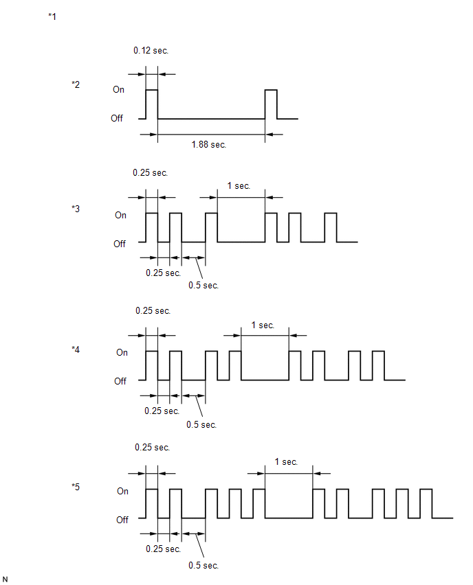
*1 |
Immobilizer Indicator |
*2 |
Normal (immobiliser system operating normally) |
*3 |
Code 2-1 |
*4 |
Code 2-2 |
*5 |
Code 2-3 |
- |
- |
Result:
Result | Proceed to |
|---|---|
Code 2-1 or code 2-3 is output |
A |
Code 2-2 is output |
B |
| B | |
END (THE REGISTERED KEY WAS USED) |
|
READ VALUE USING TECHSTREAM (TRANSPONDER S-CODE, TRANSPONDER M-CODE)
(a) Connect the Techstream to the DLC3.
(b) Turn the ignition switch to ON.
(c) Turn on the Techstream.
(d) Select the following menu items: Body Electrical / Immobiliser / Data List.
(e) Read the Data List by following the instructions on the Techstream.
Body Electrical > Immobiliser > Data ListTester display | Item | Range | Normal Condition | Diagnostic Note |
|---|---|---|---|---|
Transponder S-code |
Number of registered secondary keys |
min. 0, max. 15 |
Number of registered secondary keys |
- |
Transponder M-code |
Number of Registered Master Keys |
min. 0, max. 15 |
Number of Registered Master Keys |
- |
Tester display |
|---|
Transponder S-code |
Transponder M-code |
Result:
Result | Proceed to |
|---|---|
5 is displayed for "Transponder M-code" and 0 is displayed for "Transponder S-code" |
A |
0 is displayed for "Transponder M-code" and 3 is displayed for "Transponder S-code" |
B |
5 is displayed for "Transponder M-code" and 3 is displayed for "Transponder S-code" |
C |
The values are different from those specified above |
D |
| A | |
KEY REGISTRATION (SUB KEY) |
| B | |
KEY REGISTRATION (MAIN KEY) |
| C | |
MAXIMUM NUMBER OF KEYS ALREADY REGISTERED |
|
KEY REGISTRATION
(a) Refer to the table below to determine whether additional keys can be registered.
Number of registered keys (main and sub keys) | Proceed to |
|---|---|
0 |
Registering ID code of new key |
1 à 7 |
Registering ID code of additional key |
(b) Check whether an additional key can be registered.
OK:
An additional key can be registered.
| OK | |
END (KEY IS DEFECTIVE) |
| NG | |
REPLACE TRANSPONDER KEY ECU ASSEMBLY |
INSPECT UNLOCK WARNING SWITCH ASSEMBLY
(a) Remove the unlock warning switch assembly.
Click here
(b) Inspect the unlock warning switch assembly.
Click here
| NG | |
REPLACE UNLOCK WARNING SWITCH ASSEMBLY |
|
CHECK HARNESS AND CONNECTOR (TRANSPONDER KEY ECU ASSEMBLY - UNLOCK WARNING SWITCH ASSEMBLY)
(a) Disconnect the F13 unlock warning switch assembly connector.
(b) Disconnect the F22 transponder key ECU assembly connector.
(c) Measure the resistance according to the value(s) in the table below.
Standard resistance:
Tester Connection | Condition | Specified Condition |
|---|---|---|
F13-1 (UN+) - F22-3 (KSW) |
Always |
Below 1 Ω |
F13-2 (UN-) - Body ground |
Always |
Below 1 Ω |
F13-1 (UN+) - Body ground |
Always |
10 kΩ minimum |
F22-3 (KSW) - Body ground |
Always |
10 kΩ minimum |
| OK | |
REPLACE TRANSPONDER KEY ECU ASSEMBLY |
| NG | |
REPAIR OR REPLACE HARNESS OR CONNECTOR |