Fuses in the hood space
Opening the fuse box in the hood space
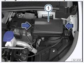
Fig. 1 In the hood space: fuse box.
Fuse box cover.
The fuse box cover may contain plastic pliers for pulling out the fuses.
Removing the cover
Open the hood.
Press the catches in the direction of the arrow → fig. 1 (arrows), to release the fuse box cover → fig. 1 (1) .
Remove the cover upward.
Fitting the cover
Place the cover on the fuse box and press it down until the cover audibly clicks into place on both sides.
- Fuse table for fuses in the hood space
- Fuses in the instrument panel
- Fuse table for fuses in the instrument panel
- Replacing blown fuses
Fuse table for fuses in the hood space
The list shows the fuse locations for the equipment relevant to the driver. The first column of the table contains the fuse slot; the other columns include the fuse version, current rating, and the protected equipment.
Depending on the country and the Volkswagen ID.3 vehicle equipment, there may be differences from the fuse numbers and fuse slots listed in the table. If necessary, ask for the exact fuse assignment from suitably qualified professionals. Volkswagen recommends contacting an authorized Volkswagen dealer or authorized Volkswagen Service Facility.
Fuse assignment
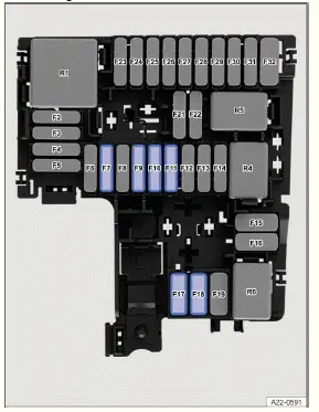
Fig. 1 In the hood space: Fuse locations.
Fuse location → fig. 1 :
F7
30 A, ATO, front right windshield wiper.
F9
15 Amp, ATO, horn.
F10
30 A, ATO, front left windshield wiper.
F11
7.5 A, ATO, air conditioner.
Fuses in the instrument panel
Opening the fuse box in the instrument panel (left-hand drive Volkswagen ID.3 vehicles)
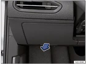
Fig. 1 Fuse box cover on the instrument panel on the driver's side (left-hand drive vehicles).
Removing the cover
Reach behind the cover and pull it off in the direction of the arrow→ fig. 1 .
Fitting the cover
Position the cover starting with the opposite side and push it closed in the opposite direction to the arrow until it clicks into place → fig. 1 .
Opening the fuse box in the instrument panel (right-hand drive Volkswagen ID.3 vehicles)

Fig. 2 On the passenger's side: Fuse box cover in the instrument panel (right-hand drive vehicles).
Removing the cover
Open the glove compartment and empty it if necessary.
Remove the cover from above in the direction of the arrow→ fig. 2 .
Fitting the cover
Insert the cover in the opposite direction of the arrow until it clicks into place at the top→ fig. 2 .
Close the glove box.
Fuse table for fuses in the instrument panel
The list shows the fuse locations for the equipment relevant to the driver. The first column of the table contains the fuse slot; the other columns include the fuse version, current rating, and the protected equipment.
Depending on the country and the Volkswagen ID.3 vehicle equipment, there may be differences from the fuse numbers and fuse slots listed in the table. If necessary, ask for the exact fuse assignment from suitably qualified professionals. Volkswagen recommends contacting an authorized Volkswagen dealer or authorized Volkswagen Service Facility.
Fuse assignment
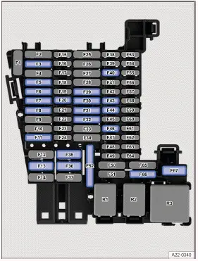
Fig. 1 Fuse assignment in the instrument panel.
Fuse location → fig. 1 :
F5
25 Amp, ATO, exterior lighting on the left side.
F6
30 Amp, ATO, interior lighting.
F7
30 Amp, ATO, seat heating.
F8
20 A, ATO, sunshade in the power sunroof.
F13
40 A, MAXI+, central locking.
F20
15 Amp, MINI, telephone, USB connection.
F30
20 A, ATO, Infotainment system scope.
F32
25 Amp, ATO, exterior lighting on the right side.
F36
40 A, MAXI+, blower regulator.
F40
7.5 Amp, MINI, anti-theft alarm system.
F43
7.5 amp, MINI, climate control bar, rear window defroster relay.
F44
7.5 A, MINI, light switch (dipped beam), rain/light sensor, ambient lighting, ID. Light.
F46
7.5 Amp, MINI, Display, Infotainment system control panel.
F52
20 Amp, ATO, sockets.
F66
15 Amp, ATO, rear window wiper.
F67
30 A, MAXI+, rear window heating.
Fuse locations in Volkswagen ID.3 vehicles with a factory installed bicycle rack mount:
F3
25 A, ATO, control module for left trailer detection.
F11
15 A, ATO, control module for trailer detection.
F29
15 A, ATO, control module for trailer detection.
F31
25 A, ATO, control module for right trailer detection.
Power windows and seats can be protected by circuit breakers or control modules, which switch back on automatically several seconds after correcting the overload, for example when door windows are frozen shut.
Replacing blown fuses
Preparations
Deactivate drive-ready mode and switch off the lights and all other electrical equipment.
Detecting blown fuses
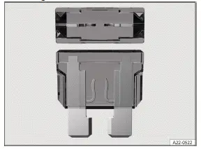
Fig. 1 Blown fuse (general example).
Shine a flashlight on the fuses.
A blown fuse can be recognized from above and from the side through the transparent casing, as its metal strip will be burnt through → fig. 1 .
Fuse versions
Standard flat connector fuse (ATO).
Small flat connector fuse (MINI).
Large flat blade fuse (MAXI or MAXI+).
Fuse color codes
Fuses (ATO - MINI - MAXI or MAXI+).
Color
Current rating
Black
1 A
Purple
3 A
Orange
5 A
Brown
7.5 A
Red
10 A
Blue
15 A
Yellow
20 A
White or clear
25 A
Green
30 A
Light green
40 A
Replacing fuses
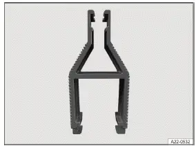
Fig. 2 Plastic pliers for removing or installing a fuse (general example).
If necessary, remove the plastic tongs from either the fuse box or the cover of the fuse box→ fig. 2 .
Depending on the design of the fuse, slide the appropriately sized clamp on the plastic pliers onto the fuse from above or from the side.
Remove the fuse.
If a fuse is blown, replace with a fuse with the same rating (same color and same label) and the same size →
 .
After inserting the new fuse, place the plastic pliers back in the cover, if necessary.
Reinstall the cover or close the fuse box cover.
NOTICE
If a fuse is replaced by a fuse with a higher current rating, this could damage the electrical system in another location.
Never replace a fuse with a fuse that has a higher current rating.
Introduction
The Volkswagen ID.3 vehicle must not be tow started for technical reasons. If the vehicle's drive system cannot be engaged because the 12 V vehicle battery is dead, the 12 V vehicle battery on another vehicle can be used to engage your vehicle's drive system.
For technical reasons, the jump-start points in electric vehicles are not designed for use in jump-starting other vehicles →  .
WARNING
Using jumper cables incorrectly and performing a jump-start incorrectly could cause the 12 V Volkswagen ID.3 vehicle battery to explode. Serious injuries may result.
Always read and heed the warnings and safety precautions before working on the 12 V vehicle battery (→ 12-V vehicle battery) .
Never confuse the positive battery terminal with the negative battery terminal.
Never jump-start a vehicle with a frozen or thawed 12 V vehicle battery.
WARNING
During a jump-start, a highly explosive gas mixture builds up at the 12 V vehicle battery. Sparks produced during a jump-start could ignite the flammable gas. Serious injuries may result.
Always keep fires, sparks, open flames, far away from the 12 V vehicle battery.
Avoid discharging static electricity near the 12 V vehicle battery.
NOTICE
The electrical system of an electric Volkswagen ID.3 vehicle is not designed to give jump-starts to other vehicles. This can cause significant damage to the electrical system of an electric vehicle.
Never use an electric vehicle to jump-start another vehicle.
NOTICE
A drained 12 V Volkswagen ID.3 vehicle battery can freeze, be damaged and fail at temperatures around approx. 0 ºC( approx. +32 ºF).
Always replace a frozen or thawed 12 V vehicle battery.