Relays and Control Modules
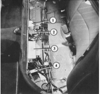
View under the rear seat of Audi 80 sedan
1 – differential lock control module (all-wheel drive models only);
2 – anti-lock braking system longitudinal acceleration switch (all-wheel drive models only);
3 – anti-lock braking system control module;
4 – auxiliary relay box.
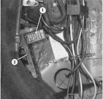
The illustration shows that the auxiliary relay box (2) under the rear seat of the Audi 80 sedan contains only the anti-lock braking system double relay (1). This relay can also be used, on vehicles equipped accordingly, as the overvoltage protection relay for the airbag ignition system. The electronic differential lock (EDS) relay can be installed in the same position. The adjacent socket 21 is usually left empty in sedans. Socket 20 contains the rear window wiper relay of the Audi 80 station wagon. Socket 19 (on the outer side of the vehicle) contains the rear fog light cut-off relay, fitted on models equipped at the factory with a towing hitch.
The electrical system includes a number of relays and control modules located in the central electrical distribution box, in the auxiliary relay box on the left under the instrument panel, or under the rear seat.
A simple switching relay is used primarily for high-current consumers. The reason is as follows: if power is routed over long cable runs through the corresponding switches, voltage losses will occur. In addition, the switch contacts are subjected to high load due to the higher current. In a relay circuit, the switch carries only a low current, and the consumer is not connected directly but through its relay.
If the switching command comes from a control module rather than a switch, the principle is the same: sensitive electronic components cannot carry high currents without being damaged.
Certain relays can perform additional functions. For example, the turn signal relay generates the flashing pulses, and the windshield washer and wiper relay controls intermittent operation and the wiper run after washing without washer fluid.
Control modules have more or less complex electronic systems for specific functions, and sometimes a relay is also installed in them. Examples are the power window control module and the interior light delay control module.
Operating Principle of a Switching Relay
When the corresponding consumer is switched on, the electrical circuit in the relay is closed from terminal 86 (incoming switching current) to terminal 85 (ground).
As a result, the electromagnet overcomes the spring force and pulls in the heavy-duty contact, thereby closing the circuit for the working current.
To prevent voltage losses, the working current is routed by the shortest path directly to relay terminal 30 and from there, with the contacts closed, through terminal 87 to the consumer.
Sometimes terminal 87a is also present. It is rigidly connected to terminal 87 and therefore performs the same function.
Troubleshooting Switching Relays
PROCEDURE
Terminal 30 must always have voltage, unless the relay's consumer depends on another consumer. Example: voltage is supplied to the rear fog light relay only when the headlights are switched on.
To check for voltage, remove (pull out) the relay and touch the probe of the test lamp to terminal 30 in the relay base. No voltage indicates an open circuit in the wiring.
Remove the relay, connect terminal 86 to the positive battery terminal and terminal 85 to ground. The electromagnet coil must clearly (audibly) pull in the relay contact; otherwise the relay is faulty.
Emergency Bypass for a Faulty Switching Relay
PROCEDURE
Remove the relay from its socket.
Connect terminals 30 and 87 in the relay socket using a paper clip or a short piece of wire. This supplies the corresponding consumer with constant current.
To deactivate, remove this jumper, as the corresponding switch is then bypassed.
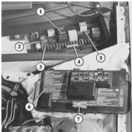
The removable cover (7) of the central electrical distribution box shows a summary diagram (6) of the possible locations of relays and fuses. The small plastic pliers for removing fuses are also located there. Inside the central electrical distribution box, the various relays (1), diagnostic connectors (2), fuses 1–21 (3), and additional fuses 23–32 (4) are visible. Four spare fuses (5) are located there as well.
Test yourself
A quick Audi 80 quiz: every answer comes with an explanation and a link to the manual page.