GENERAL INFORMATION
Specifications
General Specifications
CAUTION
Individual specifications are also given in the text of the chapter, and where their observance is mandatory they are printed in bold12 V Incandescent Bulbs
To be able to replace a bulb at any time, always carry a box with the most important spare bulbs in the vehicle.

Location of Relays and Fuses
The location of relays and fuses may differ depending on vehicle equipment and model year.
The relays are located on the relay board, behind the left cover in the footwell area, under the instrument panel. On vehicles with extensive equipment, the relay box is located behind the relay board.
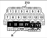 Relay Board -R- (relays shown in dark color)
Relay No. Component I Two-tone horn relay II X-contact load relay III Wiper interval control relay IV Fuel pump relay or glow plug relay V Diesel injection system relay VI Fog light relay A Heated seat fuse B Not used C Power window fuse
Additional Relay Box -Z13- above the relay board
1 Horn relay 2 Rear warning lamp monitor relay 3 Rear warning lamp monitor relay 4 Mirror cover control unit 5 Mirror cover control unit 6 Telephone isolation relay 7 Not used 8 Not used 9 Not used 10 Not used 11 Starter lock and reverse light relay 12 Headlight washer relay 13 Radiator fan freewheel relay (air conditioning)
Main Fuse Box
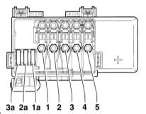 Main fuse box fuse locations 1 S131 Glow plug heater (diesel engine) 2 S132 Engine control system 3 S133 Coolant fan 2 4 S134 Interior 5 S138 Generator 1a S162 ABS (hydraulic pump) 2a S163 ABS (valves) 3a S164 Coolant fan
Fuse Color Coding
Current, A Fuse color 5 Beige 7.5 Brown 10 Red 15 Blue 20 Yellow 25 White 30 Green
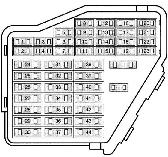 Fuse Locations in the Fuse Box
Fuse locations depend on vehicle equipment and model year. Fuse locations are shown on the fuse box cover.
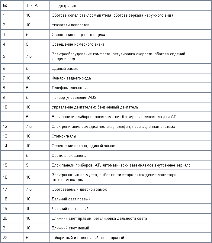
 Fuse locations are shown on the fuse box cover.
NOTE: Fuses in the fuse box are numbered 223 for position 23 on the diagram, fuse 24 is numbered 224, and so on.
Other fuses and relay locations are given in the Wiring Diagrams section.
Tightening torques for threaded connections
Fastener tightening torques are also given in the text of the Chapter and in some illustrations*.
*Torques given in bold in the text must be strictly observed; torques not in bold are given for reference only.
Vehicles of this make are equipped with a 12 V electrical system with negative ground. All lighting and electrical units are powered by a lead-acid battery recharged by an alternator.
This Chapter describes service and repair procedures for certain on-board electrical system components, including all lighting and electrical accessories not directly related to the engine. In addition, general electrical fault diagnosis procedures are covered.
CAUTION
Before performing any repair or maintenance work on electrical system components, always disconnect the negative cable from the battery to avoid electric shock and/or fire.Test yourself
A quick Audi A3 quiz: every answer comes with an explanation and a link to the manual page.