Cruise Control System Components
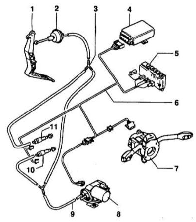 Cruise control component connection diagram 1 – Accelerator pedal 2 – Throttle actuator 3 – T-piece 4 – Cruise control module (J213) 5 – Relay carrier 6 – Wiring harness 7 – Cruise control on/off switch (E45) 8 – Cruise control vacuum pump (V18) 9 – Vacuum hose 10 – Clutch vacuum vent valve switch (F36) C – with clutch pedal position switch Only vehicles with manual transmission 11 – Brake vacuum vent valve switch (F47)
Refer to the illustration and the cruise control wiring diagram.
The wiring diagrams below are arranged on a schematic principle, where the components of each circuit are connected by the shortest route, without regard to the routing of wiring around components and harnesses.
Audi A3 uses a single-wire circuit system for electrical components. Consumers are connected to the positive supply with a wire and to ground through the vehicle body. This method reduces the number of wires and simplifies installation. Connecting the negative supply to ground reduces electrochemical corrosion of metal body parts. In some cases a direct ground connection is not sufficient, and the consumer is grounded with an additional wire, usually brown.
Power to most consumers is supplied through the ignition switch. Circuits for components that may be needed at any time are always connected to the battery, regardless of the ignition key position.
Flat-blade contact electrical connectors are used to connect wires.
For proper operation of consumers, the electrical circuit must be closed. Otherwise current will not flow. For example, if positive voltage is applied to the wiper motor, it will not operate until its circuit is connected to ground. Switches, relays, fuses, measuring instruments, electric motors and other consumers can be connected to the electrical circuit. For correct connection, the electrical connector contacts have corresponding markings. The vehicle ground connection is made either directly through the housing of the consumer or by an additional wire.
Terminal 30
This terminal always has battery positive voltage. Wires connected to this terminal are red or red with a stripe.
Terminal 31
This terminal is connected to vehicle ground with a brown wire.
Terminal 15
Positive voltage is applied to this terminal after the ignition is switched on. Wires connected to this terminal are green or green with a stripe.
Terminal X
Voltage is applied to this terminal after the ignition is switched on, but it is cut off when the starter is engaged. This allows consumers not needed during engine starting to be switched off. The high beam headlights are also powered from this terminal, so when the high beams are on and the ignition is switched off, the system automatically switches to the parking lights.
Wire colors are designated by Latin letters.
If the wire color designation contains several letters separated by the / sign, the left group of letters indicates the base color of the wire and the right group indicates the stripe color.
bl Blue
br Brown
el Cream
ge Yellow
gn Green
gr Grey
hbl Light blue
hgn Light green
li Lilac
nf Natural (clear)
og Orange
rbr Burgundy
ro, rt Red
rs Pink
sw Black
vi Violet
ws White
All consumers and switches are shown in the neutral position in the diagram.
Test yourself
A quick Audi A3 quiz: every answer comes with an explanation and a link to the manual page.