Oxygen Sensor (L-Sensor) Inspection
The L-sensor (wide-range or narrow-band oxygen sensor) located in the engine exhaust system monitors the oxygen content in the exhaust gas flow. When O2 molecules come into contact with the sensing element of the sensor, the sensor generates a voltage signal in the range of 0.1 to 0.9 V, depending on the oxygen concentration. A value of 0.1 V corresponds to a high O2 content (lean mixture), and a value of 0.9 V corresponds to a low O2 content (rich mixture). The PCM continuously monitors the signal received from the oxygen sensor and, when necessary, issues commands to correct the air-fuel mixture composition by changing the injector pulse duration. The optimal air-fuel ratio, which ensures minimum fuel consumption and the most efficient operation of the catalytic converter, is 14.7 parts of air to 1 part of fuel. The control module constantly strives to maintain this ratio, based on information received from the L-sensor. On the vehicles in question, two oxygen sensors are used: the primary sensor is located in the engine exhaust manifold, and the secondary sensor is located downstream of the catalytic converter. By comparing the oxygen content levels upstream and downstream of the catalytic converter, the PCM also determines the efficiency of the catalytic converter.
It should be noted that the oxygen sensor is capable of generating a signal voltage only when heated to its normal operating temperature (approximately 320°C). While the sensor is cold, the PCM operates in OPEN LOOP mode.
If, with the engine at normal operating temperature and/or running for at least two minutes, the oxygen sensor generates a stable signal with an amplitude below 0.45 V (at engine speeds of at least 1500 rpm), the self-diagnostic system stores the corresponding fault code in the PCM memory (P0131 or P0132). The corresponding code is also stored if a fault is detected in the sensor heater circuit (refer to Section On-Board Diagnostics (OBD) - Operating Principle and Diagnostic Trouble Codes).
If the L-sensor or its circuit malfunctions, the PCM switches to open loop mode, ignoring the information received from the sensors and maintaining the air-fuel mixture at a predetermined level that provides sufficient engine output.
Correct operation of the oxygen sensor depends on the fulfillment of a number of specific conditions:
a) Electrical parameters: The stability of the low-voltage amplitude signal generated by the sensor depends to a large extent on the quality of the contact connections in the L-sensor circuit. These connections should be checked first if problems occur;
b) Outside air supply: The L-sensor design provides for free circulation of outside air inside the sensor. When installing the sensor, always check that the air passages are clear;
c) Operating temperature: The PCM begins to respond to information received from the L-sensor only after the sensor has reached normal operating temperature (approximately 320°C). This must be kept in mind when checking the sensor operation;
d) Fuel quality: Correct operation of the L-sensor is possible only if UNLEADED fuel is used to refuel the vehicle!
In addition to the conditions listed in the previous paragraph, the following special precautions must be observed when servicing the L-sensor:
a) The oxygen sensor is equipped with a pigtail wire permanently attached to it and fitted with a connector plug. Attempting to disconnect it may cause irreversible sensor failure;
b) Do not allow dirt or grease to get into the sensor slots or its electrical connector;
c) Do not use any solvents to clean the oxygen sensor;
d) Handle the L-sensor with extreme care. Do not drop it or shake it;
e) The silicone protective boot must be installed on the sensor in the specified manner so that it does not melt and does not impair sensor operation.
INSPECTION
PROCEDURE
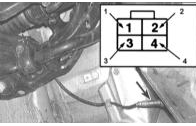
1. Locate the sensor electrical connector. From the back of the connector, insert a straightened paper clip into the signal wire terminal cavity (terminal No. 1 [+]), and insert a second paper clip into the terminal No. 2 (ground) cavity. Connect the positive probe of a voltmeter to the first paper clip and the negative probe to the paper clip inserted into the ground terminal. Apply the parking brake, place the AT selector lever in the "P" position, and on models with a manual transmission select neutral. Raise the front of the vehicle and support it on safety stands.
2. Start the engine and begin monitoring changes in the oxygen sensor signal voltage.
Avoid touching hot surfaces of the exhaust system.
Slower voltage fluctuations of the downstream (rear) O2 sensor result from the action of the catalytic converter, since the bound oxygen atoms in CO2 and H2O molecules affect the sensing element of the sensor to a much lesser degree than the atoms in CO and NOX molecules.
3. Initially, a cold sensor should output a steady signal of 0.1 ÷ 0.2 V (open loop mode). After approximately two minutes, the engine will reach normal operating temperature and the sensor reading will begin to fluctuate between 0.1 and 0.9 V (closed loop mode). If the system does not enter closed loop mode, or enters it with an excessive delay (lazy sensor), replace the upstream (front) O2 sensor.
4. Also check the operation of the oxygen sensor heater. Disconnect the sensor wiring connector and connect an ohmmeter between the heater terminals (terminals No. 3 and 4). Nominal resistance is 10 ÷ 40 Ohm.
5. Check the power supply to the heater. Disconnect the electrical connector and measure the voltage at the harness side between terminal No. 4 and ground. With the ignition on (do not start the engine), the voltmeter should read battery voltage. If there is no power, check the wiring between the main relay, PCM and the oxygen sensor.
6. If the above checks give negative results, replace the faulty upstream O2 sensor.
Test yourself
A quick Honda Accord quiz: every answer comes with an explanation and a link to the manual page.