Body Electrical System
Power Liftgate Module
In this manual: Body Electrical System
8steps
~48min
3/5difficulty
Done 0 of 8
Components and Component Location
Components
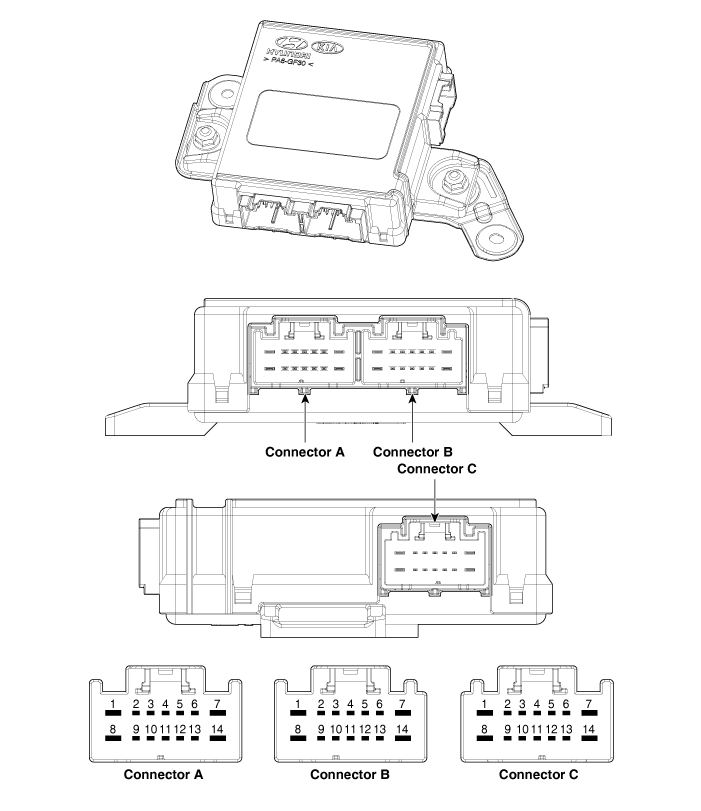
| No. | Connector A | Connector B | Connector C |
| 1 | Power Supply | Latch Motor (+) | Spindle Motor (RH)_Close (-) |
| 2 | Lighting (Liftgate Inside Switch) | Liftgate Full Open Switch | Hall Sensor (RH)_Power |
| 3 | - | Liftgate Full Close Switch | Spindle (LH) Shield_Ground |
| 4 | B-CAN (High) | Liftgate Half Latch Switch | Hall Sensor (RH)_Ground |
| 5 | B-CAN (Low) | Home Position Switch_Ground | Spindle (RH) Shield_Ground |
| 6 | Buzzer | Liftgate Lock Switch_Ground | Hall Sensor (LH)_Power |
| 7 | - | System Ground | Spindle Motor (LH)_Close (+) |
| 8 | Liftgate Motor | Latch Motor (-) | Spindle Motor (RH)_Close (+) |
| 9 | - | Liftgate Open/Close Switch | Hall Sensor 1 (RH) |
| 10 | Gear Position N | Liftgate interior switch | Hall Sensor 2 (RH) |
| 11 | - | Home Position Switch | Hall Sensor (LH)_Ground |
| 12 | Anti-Pinch Strip (LH) Power | Anti-Pinch Strip (LH)_Ground | Hall Sensor 1 (LH) |
| 13 | Anti-Pinch Strip (RH) Power | Anti-Pinch Strip (RH)_Ground | Hall Sensor 2 (LH) |
| 14 | - | Power Ground | Spindle Motor (LH)_Close (-) |
Circuit Diagrams
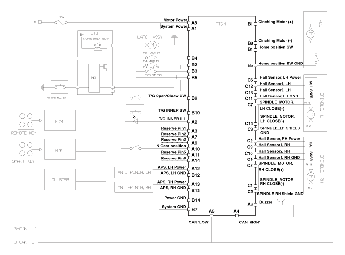
Wiring Diagram
Repair Procedures
Removal
Disconnect the negative (-) battery terminal.
Remove the rear side trim panel [LH].
(Refer to Body — "Luggage Compartment Side Trim")
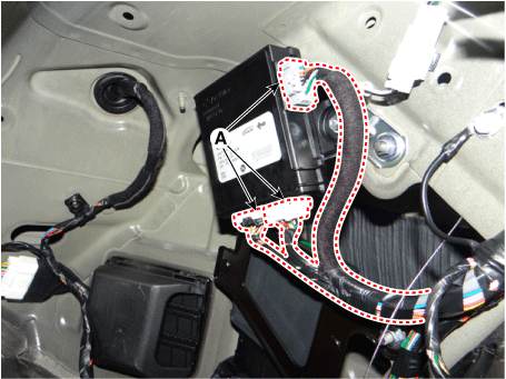
Disconnect the power liftgate module connectors (A).
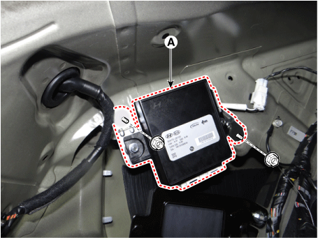
Remove the power liftgate module (A) after loosening the mounting nuts.
Installation
Install the power tailgate module.
Connect the power liftgate module connectors.
Install the luggage compartment side trim panel [LH].
Connect the negative (-) battery terminal.
Inspection
Inspection Power Liftgate Module
Refer to Power Liftgate System - Troubleshooting.
Test yourself
A quick Kia Stinger CK quiz: every answer comes with an explanation and a link to the manual page.
Was this page helpful?