Valve Clearance Inspection and Adjustment
GENERAL INFORMATION
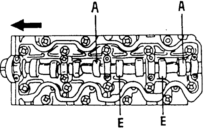
Valve clearance adjustment sequence when the No. 1 piston is at TDC

E – intake camshaft
A – exhaust camshaft
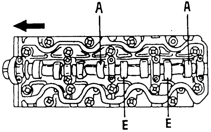
Valve clearance adjustment sequence when the No. 4 piston is at TDC
E – intake camshaft
A – exhaust camshaft
Use of special service tool to press the tappets into their bores
E – intake camshaft
A – exhaust camshaft
Use of special service tool to press the tappets into their bores
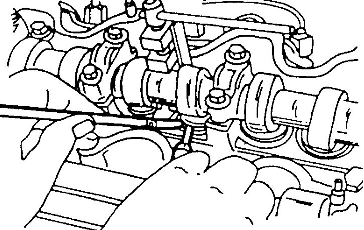
A screwdriver and a magnet are used to remove the adjusting shims.
On diesel engines, valve clearances are inspected and adjusted with the engine cold.
PROCEDURE
1. Remove the cylinder head cover.
2. Turn the engine until the No. 1 piston is at TDC. The mark on the pulley must align with the pin on the oil pump housing.
3. Check that the valve tappets of cylinder No. 1 have slight play, and the valve tappets of cylinder No. 4 are tight. If not, turn the engine one more revolution.
4. Measure the valve clearances using feeler gauges inserted between the tappet and the cam surface, as shown in the figure Valve clearance adjustment sequence when the No. 1 piston is at TDC. Intake (E) and exhaust (A) valve clearances are not the same on all engines and are given in the specifications tables.
5. Turn the engine one full revolution and measure the clearances shown in the figure Valve clearance adjustment sequence when the No. 4 piston is at TDC. The correct adjustment is indicated when the feeler gauge tip enters, and then, under light pressure, the gauge bends and goes in.
6. To adjust the valve clearances, the adjusting shims on the top of the tappets must be replaced. Removing and installing the adjusting shims requires special tools. Turn the crankshaft until the corresponding cam lobe points upward, then use the special service tool shown in the figure to press the tappet down, or otherwise press the tappet inward, so that the adjusting shim can be removed with a small screwdriver and a magnet.
7. Before pressing the tappet, turn it so that the notch on its upper side faces the spark plugs. Both tappets must be pressed simultaneously, making sure both tappets are pressed by the tool leg.
8. Measure the removed shim with a micrometer and record the result.
9. Calculate the thickness of the new shim required to obtain the specified valve clearance using the following formula:
Intake valves: N = T + (A – 0.25 mm);
Exhaust valves: N = T + (A – 0.30 mm), where T is the thickness of the removed shim, A is the measured valve clearance, and N is the thickness of the new shim to be installed.
10. Select the shim whose thickness is closest to the required value. A series of 25 shim sizes is available, from 2.2 mm to 3.4 mm in 0.05 mm increments.
11. To install the adjusting shim, press the tappet down again and insert the shim.
12. Measure the valve clearance as described above.
13. Adjust the clearances of the remaining valves.
* The adjusting shim must never fall into the engine. To prevent this, use a small screwdriver and a magnet, as shown in the figure Use of special service tool to press the tappets into their bores. The shim can then be slid to the side and caught with the magnet.
Test yourself
A quick Toyota Corolla quiz: every answer comes with an explanation and a link to the manual page.