Lubrication System
GENERAL INFORMATION
The lubrication system is supplied by a trochoid oil pump. The pump design is shown in the figure. Oil pump assembly drawing.
Removal, Disassembly and Installation of Oil Pump

Oil pump assembly drawing 1. Drive gear
2. Oil pump
3. Relief valve
4. Spring
5. O-ring
6. Drive rotor
7. Driven rotor
8. Oil seal
9. Plug
PROCEDURE
1. To access the pump, remove the timing belt, idler pulley and crankshaft gear. Also remove the oil pan.
2. The oil pump is secured with bolts on the front side of the engine and sealed with an O-ring. The bolts are of different lengths.
3. To separate the oil pump from the inside of the crankcase, use a plastic hammer.
4. Installation is performed in reverse order. Be sure to install a new O-ring. Apply sealant to the pump housing surface, making sure it does not get into the bolt holes.
5. Install the pump and tighten the eleven bolts together with the alternator bracket to 18 N·m. Do not mix up the bolts. Do not damage the oil seal during installation.
6. If the oil strainer was removed, install it with a new gasket. Tighten the nuts to 7 N·m and the bolts to 13 N·m.
6. Clean the cylinder block and oil pan surfaces and install the oil pan as described in subsection 3.1.1.12.
Inspection
7. First mark the surfaces of the driven rotor, then remove it from the housing.
8. Clamp the drive gear in a vise with soft metal jaws and loosen the nut with an open-end wrench. Remove the pump gear and pull out the driven rotor.
9. From the bottom side, remove the plug and take out the relief valve parts. Clean all parts thoroughly and replace if necessary. The oil seal in the housing must always be replaced (carefully pry it out with a screwdriver).
Check the rotor tips for chipping. Rotors must always be replaced as a set.
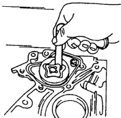
10. Insert the outer rotor into the bore and measure the clearance between the outer surface of the outer rotor and the pump bore with a feeler gauge. The clearance must not exceed 0.2 mm. For the next check, insert a feeler gauge between the tip of the outer rotor tooth and the tip of the inner rotor tooth. The clearance must not exceed 0.20 mm. Otherwise, replace the oil pump and/or rotors (as a set).

11. Place a straightedge on the housing surface and measure the clearance between the straightedge and the rotors with a feeler gauge. The clearance must not exceed 0.20 mm. Otherwise, replace the oil pump and/or rotors (as a set).
12. Assemble the oil pump in reverse order. Install the outer rotor with the marked surface facing out. Install the inner rotor and fit the pump drive gear onto the rotor shaft. Screw on the nut and clamp the drive gear in the vise again. Tighten the nut to 47 N·m.
13. Pour pre-lubricating oil into the pump bore to lubricate the rotors. Install the relief valve parts and screw in the plug. Lubricate the seal lips and press the seal into the pump housing flush.
Oil Filter
Oil filter replacement is performed the same way as on gasoline engines (see subsection 3.1.1.12).
Checking the engine oil level
For operation description, see subsection 2.3. Special oils are used for filling the diesel engine.
Test yourself
A quick Toyota Corolla quiz: every answer comes with an explanation and a link to the manual page.