Air Mix Control Motor Circuit

Disconnect the wiring from the motor assembly. Using a jumper wire, apply battery voltage to terminal 1 of the motor connector and ground terminal 2. The motor should start to rotate; if not, swap the jumper wires, which should make the motor rotate in the opposite direction. A faulty motor must be replaced. Next, measure the resistance between connector terminals 5 and 7 (specified value 4.2 ÷ 7.8 kΩ) and terminals 3 and 5 (0.58 ÷ 1.09 kΩ when cold air is selected to the cabin and 3.52 ÷ 6.55 kΩ when maximum heating is selected).
If there is doubt about the door operation, disconnect the motor actuator rod from the operating link and repeat the check above using jumper wires. If the motor now operates correctly, replace the door or its link.
Mode Selection Motor
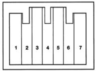
Check by applying battery voltage to terminal 2 and grounding terminal 1 of the motor. The motor should run to its stop and then stop, after which the power supply must be disconnected immediately. Reversing the polarity of the jumper wires should cause the motor to rotate in the opposite direction.
If a digital multimeter is available, set it to resistance measurement mode (range up to 20 kOhm with an output current of no more than 1 mA) and check for continuity between the connector terminals during the procedure. Continuity should appear instantly between terminal 7 and terminals 3, 4, 5 and 6.
If the motor rotates too slowly or does not rotate at all, disconnect its actuator rods from the corresponding damper and repeat the test. If the motor now rotates normally, find and eliminate the cause of the damper or damper rod binding.
Recirculation Mode Motor
Disconnect the wiring from the motor.
Using a jumper wire, apply battery voltage to terminal 1 of the motor and ground terminals 5 and 7. The motor should rotate smoothly and move to one of its two extreme positions ("Recirculation" or "Fresh Air Intake") when the ground is disconnected.
If the motor rotates too slowly or does not rotate at all, disconnect its actuator rods from the corresponding damper and repeat the test. If the motor now rotates normally, find and eliminate the cause of the damper or damper rod binding.
Vehicles Equipped with Climate Control System
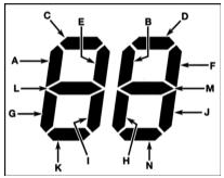
These models use a more advanced self-diagnostic system. Instead of a warning lamp, an LED temperature display on the control panel is used, capable of showing up to 40 fault codes. During the diagnostic check, two "88" symbols are displayed. Each segment of both symbols corresponds to a specific fault in the system.
Turn the ignition on, move the temperature control lever to the minimum temperature position, then move it to the maximum heat position. Wait one minute, then press the "AUTO" button on the control panel. While holding the "AUTO" button, also press the "OFF" button. The temperature display should show two "88" symbols.
When the self-diagnostic system detects a standard fault, the corresponding segment of one of the symbols will flash. Record the flashing segments according to the designations shown in the illustration above. Using the fault code chart, determine the nature of the fault and prepare to perform the appropriate repair.
Eliminating A/C System Odors
Unpleasant odors, often occurring when the A/C is switched on, are caused by mold colonies forming on the evaporator core fins. A warm, humid environment creates the most favorable conditions for the development and growth of fungal microorganisms.
Access to the evaporator core is extremely limited on most models. A procedure to completely remove mold, performed at a repair shop, is labor-intensive, time-consuming, and requires strong disinfectants. In principle, sufficiently effective treatment can also be carried out at home by the vehicle owner.
Special aerosol disinfectants designed for A/C systems can be purchased at almost any automotive accessories store. Keep in mind that the price of the product is usually directly proportional to its effectiveness. Switch the system to recirculation mode and run the heater blower at maximum speed for ten minutes. To dry the system, turn the heat to maximum. Disconnect the wiring from the A/C compressor to prevent it from engaging (refer to Section A/C Compressor Removal and Installation).
The product is usually applied through a long hose. Remove the heater blower motor (refer to Section Heater Blower Motor Removal and Installation). Insert the application nozzle into the opening that is formed and move it to the left, directing it at the evaporator core. Apply the product in accordance with the manufacturer's instructions. Try to treat the entire surface of the evaporator core as thoroughly as possible. The duration of each treatment cycle and the intervals between cycles should be specified on the product label.
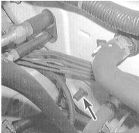
The best preventive measure against mold colonies forming in the evaporator core is to regularly check that the condensate drain tube is clear and free-flowing.
Test yourself
A quick Honda Accord quiz: every answer comes with an explanation and a link to the manual page.