Component | General Description |
Engine Switch
- Transponder key amplifier
|
- Activates the power supply and starts the engine.
- Contains a built-in transponder amplifier to start the engine when the electronic key transmitter assembly does not operate properly due to a discharged transmitter battery or radio wave interference.
|
Certification ECU (Smart Key ECU Assy) |
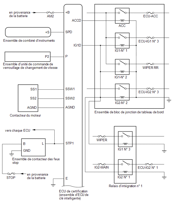
- Changes the power source mode by operating the ACC and IG relays.
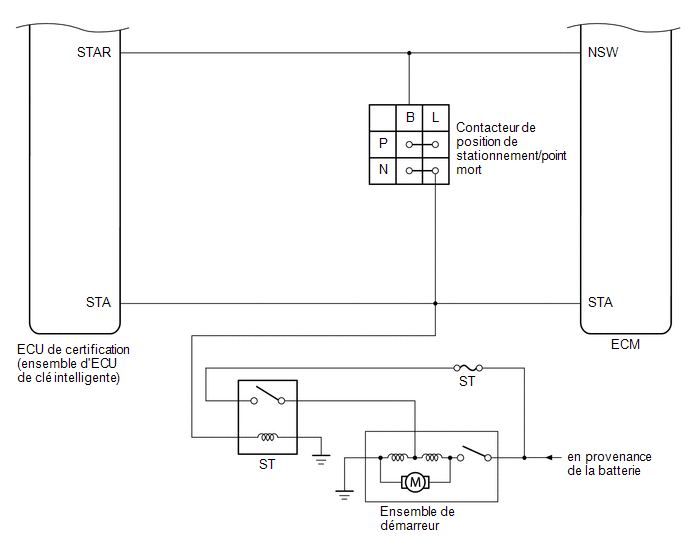
- Controls engine starting by operating the starter relay.
- Performs a key verification.
- Controls each electronic key antenna (outside), the electronic key antenna (inside), and the door lock/unlock sensor.
- Outputs door lock/unlock control commands when the door is opened.
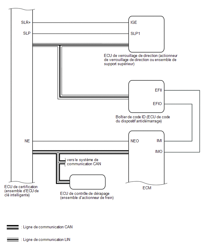
- Transmits activation/deactivation control signals to the steering lock ECU (steering lock actuator or upper support assembly).
- Outputs activation/deactivation control commands to the immobilizer system.
- Generates the detection area of the smart key system.
|
ID Code Box (Immobilizer ECU) |
- Receives control signals from the certification ECU (smart key ECU assembly) and outputs immobilizer activation/deactivation control signals to the ECM.
- Stores smart verification codes.
|
ECM |
Outputs a signal indicating that the engine has started to the certification ECU (smart key ECU assembly) when the engine starts. |
Steering lock ECU (steering lock actuator or upper bracket assembly) |
- Receives control signals from the certification ECU (smart key ECU assembly) and activates the steering lock ECU (steering lock actuator or upper support assembly).
- Stores smart verification codes.
|
Combination meter assembly |
- Displays various warnings (multi-information display messages) based on the control signals sent from the certification ECU (smart key ECU assembly).
- Sends a vehicle speed signal to the ECUs.
|
IG, ACC relays |
Turns on/off based on the control command from the certification ECU (smart key ECU assembly) and supplies power to each system. |
Stop light switch assembly |
Detects when the brake pedal is depressed (switch in ON position) and transmits a signal to the certification ECU (smart key ECU assembly). |
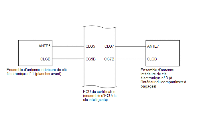
- No. 1 Interior Electronic Key Antenna Assembly (Front Floor)
- No. 3 Interior Electronic Key Antenna Assembly (Luggage Compartment Interior)
|
Sends the request code from the certification ECU (smart key ECU assembly) and generates a detection area inside the vehicle. |
Electronic Key Transmitter Sub-assembly |
Sends an ID code when a request signal is received. |
Park/Neutral Position Switch |
Outputs a shift lever engaged signal to the certification ECU (smart key ECU assembly). |
Shift lock control unit assembly |
Outputs a shift lock control ECU signal to the certification ECU (smart key ECU assembly). |
Electronic Key and TPMS Receiver Assembly |
Receives the smart key system code/remote control code transmitted by the electronic key transmitter assembly and sends it to the certification ECU (smart key ECU assembly). |