Selection of Crankshaft Main and Connecting Rod Bearings
If the main bearing shells are worn or damaged, or if the correct bearing clearance cannot be obtained (refer to Crankshaft Installation and Main Bearing Clearance Check or Piston and Connecting Rod Assembly Installation and Crankshaft Connecting Rod Bearing Clearance Check), the situation can be corrected by selecting and installing new bearing shells as described below. If the crankshaft has been machined undersize, it must be fitted with bearing shells of the corresponding undersize repair dimensions (in this case the procedure below must not be performed). Bearing selection is usually carried out by the specialists who machined the crankshaft journals. Regardless of the method used to determine the required bearing size, the bearing working clearances must then be checked using Plastigage measuring kit (see below).
If the bearing clearance cannot be correctly adjusted by selecting bearing shells, the crankshaft must be replaced.
Main Bearings
1. When selecting new STANDARD size bearing shells, choose the shell with the same color code as the old one.
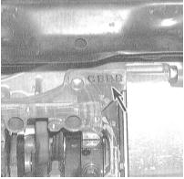
2. If the color code on the old bearing insert is lost, locate the mark stamped on the block in the area of the corresponding bearing cap.
3. Also check the main bearing class mark on the crankshaft itself.
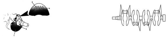
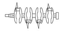
4. When selecting new bearing inserts, use the corresponding bearing color code identification chart.
Connecting Rod Bearings
1. When selecting new STANDARD size bearing inserts, refer to the color codes of the components removed from the vehicle.
2. If the color code on the old inserts is lost, locate the mark on the lower connecting rod ends. A numeric mark indicates the size class of the connecting rod bearing (do not confuse it with the cylinder number).
3. Also check the letter marks on the crankshaft itself, which specify the size of the corresponding connecting rod journals (see the accompanying illustration).
Main bearing insert selection chart for 4-cylinder engine crankshafts - use the mark stamped on the engine block and the crankshaft assembly. For example, mark C3 means that yellow and green inserts must be installed (where they must be of different colors). Either insert may be installed in the bearing cap or in its bore in the block
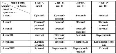
Main Bearing Insert Selection Chart for V6 Engine Crankshafts
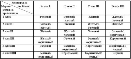
On 4-cylinder engines, the letter-number mark for the main journal class is stamped on the counterweight of the first crank throw or stamped adjacent to each individual journal.
4. When selecting new bearing inserts, use the corresponding bearing color code identification chart.
Connecting rod bearing insert selection chart for 4-cylinder engine crankshafts - use the mark stamped on the crank throws and the corresponding connecting rods. For example, mark D4 means that blue inserts must be installed
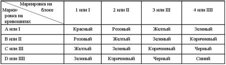
Connecting rod bearing insert selection chart for V6 engine crankshafts - use the mark stamped on the crank throws and the corresponding connecting rods. For example, mark D4 means that brown inserts must be installed (note that in some cases a combination of two different colored inserts is required)
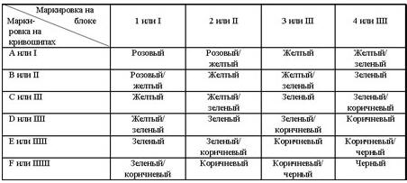
All Bearings
Remember that the final criterion determining correct insert selection is the result of measuring the operating clearances in the bearings. If you have any questions, do not hesitate to contact authorized Honda service centers.
Test yourself
A quick Honda Accord quiz: every answer comes with an explanation and a link to the manual page.