Installation of Connecting Rod and Piston Assemblies and Checking Connecting Rod Bearing Oil Clearance
Preparation
PROCEDURE
1. Before installing the connecting rod and piston assemblies, thoroughly wipe the cylinder walls and completely remove any step wear from their upper edges and chamfer them. It is assumed that the crankshaft is already installed in its normal position in the block.
2. Remove the lower connecting rod cap for the No. 1 cylinder piston (make sure the factory or removal alignment marks are present). Remove the old bearing inserts from the connecting rod and its cap, and thoroughly wipe their seats with clean lint-free cloth.
Checking Connecting Rod Bearing Oil Clearance
PROCEDURE
Avoid touching the surfaces of new bearing inserts with bare hands to prevent unwanted contact of the bearings with oil and chemically aggressive substances that are always present on fingers.
1. Wipe the back of the new upper bearing insert and seat it in the connecting rod bearing bore. Make sure the locating tang of the insert engages the matching groove in the connecting rod. Never tap the insert into its seat with a hammer. Do not lubricate the bearing at this stage.
2. Wipe the back of the second insert and seat it in the lower connecting rod cap. Again make sure the tang engages the matching slot. Do not apply any lubricant - it is extremely important that the mating surfaces of the bearing and connecting rod remain absolutely clean and dry.

3. Position the piston rings with their end gaps as shown in the illustration.
NEVER position the ring gaps in line with the piston pin or perpendicular to its axis!
4. Lubricate the piston and piston rings with clean engine oil.
5. Install the piston ring compressor sleeve onto the piston. Leave the piston skirt protruding from the tool sleeve by approximately 6.4 mm to allow free entry into the cylinder. The rings must be compressed flush with the piston outer surface.
6. Rotate the crankshaft so that the No. 1 crankpin is at BDC. Lubricate the No. 1 cylinder bore with engine oil.
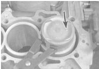
7. With the arrow or recess mark on the piston crown facing the front of the engine, carefully insert the connecting rod into the No. 1 cylinder bore. Place the piston skirt into the cylinder, firmly pressing the lower edge of the ring compressor sleeve against the block surface.
8. Tap the upper edge of the sleeve to ensure it sits tightly against the block around the entire lower edge perimeter.
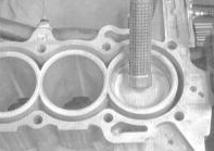
9. Carefully tap the piston crown with the wooden handle of a hammer to guide the piston into the cylinder while simultaneously guiding the lower connecting rod end onto the corresponding crankpin. The piston rings may suddenly pop out from under the tool sleeve, so constantly monitor that the sleeve remains tight against the block. Work unhurriedly; at the slightest resistance, stop tapping the piston immediately. Determine the cause of the binding and correct it. Never attempt to force the piston into the cylinder, as this may cause mechanical damage to the piston or break the piston rings.
10. After inserting the connecting rod and piston assembly into the engine, and before final installation of the lower connecting rod cap, check the connecting rod bearing oil clearance on the crankshaft.
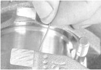
11. Cut a piece of calibrated plastic gauge (Plastigage) from the measuring kit, slightly shorter than the width of the connecting rod bearing insert, and lay it along the No. 1 connecting rod journal of the crankshaft, parallel to the journal axis.
12. Wipe the bearing surface in the lower connecting rod cap and install the cap on the connecting rod. Make sure the mark on the cap faces the same direction as the mark on the connecting rod.
13. Install the cap bolts and tighten them in three steps to the specified torque.
To avoid wrench binding, use a thin-wall socket. If the wrench begins to bind between the bolt head and the connecting rod, lift the head slightly and continue tightening. Do not rotate the crankshaft during the entire procedure.
14. Remove the bolts and carefully remove the cap from the connecting rod. Take care not to damage the flattened piece of calibrated gauge.
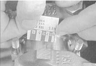
15. Using the scale printed on the Plastigage package, measure the width of the flattened gauge to determine the bearing oil clearance. Compare the measured result with the Specifications.
16. If the clearance is outside the permissible range, before selecting bearing inserts of a different undersize, check whether dirt or oil has got under the backs of the inserts seated in the connecting rod and cap. Measure the journal diameter again. If the gauge is flattened more at one end than the other, the journal is tapered.
Test yourself
A quick Honda Accord quiz: every answer comes with an explanation and a link to the manual page.