Accelerator Pedal Position Sensor (APS)
Specifications
Specification
| Accelerator Position |
Output Voltage (V) [Vref = 5 V] | |
| VPA1 | VPA2 | |
| THA | 0,7 - 0,8 | 0,33 - 0,43 |
| THW | 3,99 - 4,23 | 1,94 - 2,18 |
Description and Operation
Description
The accelerator position sensor (APS), installed on the accelerator pedal module, detects the angle of the accelerator pedal. Since the APS is one of the most important sensors in the engine control system, each of its two sensors has an independent power supply line and ground line. APS 2 monitors APS 1, and its output voltage is half that of APS 1. If the ratio between APS 1 and APS 2 goes outside the allowable range (approximately 1/2), the diagnostic system regards this as abnormal.

Circuit Diagrams
Wiring Diagram

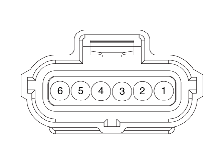
Harness Connector
Repair Procedures
Inspection
Connect the KDS to the Data Link Connector (DLC).
Turn the ignition switch ON.
Measure the output voltage of APS 1 and 2 at C.T. and W.O.T.
Accelerator
PositionOutput Voltage (V) [Vref = 5 V] VPA1 VPA2 THA 0,7 - 0,8 0,33 - 0,43 THW 3,99 - 4,23 1,94 - 2,18
Removal
Turn the ignition switch OFF and disconnect the negative (-) battery terminal.
Disconnect the accelerator position sensor connector (A).
Remove the accelerator pedal position sensor (C) after loosening the mounting bolt and nut (B).
Accelerator pedal position sensor mounting bolt:
8,8–13.7 N·m

Installation
Install in the reverse order of removal.
Test yourself
A quick Kia Stinger CK quiz: every answer comes with an explanation and a link to the manual page.